Developing device with airflow

Active Publication Date: 2020-05-26
FUJIFILM BUSINESS INNOVATION CORP
View PDF14 Cites 1 Cited by
  • Summary
  • Abstract
  • Description
  • Claims
  • Application Information

AI Technical Summary

Benefits of technology

[0007]According to an aspect of the present disclosure, there is provided a developing device including a toner holding member that rotates while holding a toner on an outer peripheral surface of the toner holding member and develops an electrostatic latent image formed on an image carrier, a control member that controls a thickness of a layer of the toner formed on the outer peripheral surface of the toner holding member, a suppression member

Problems solved by technology

In the case where the toner that has accumulated in the suppression member falls, in the form of, for example, a lump, onto the toner holding member, this causes an image quality defect such as a streak in an image that is formed.
Howev

Method used


Image

  • Developing device with airflow
  • Developing device with airflow
  • Developing device with airflow

Examples


Example

[0017]An exemplary embodiment of the present disclosure will be described below with reference to the accompanying drawings.

1>

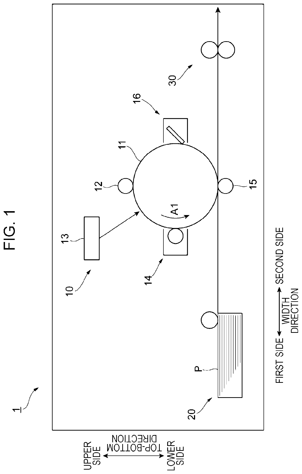
[0018]FIG. 1 is a diagram illustrating the overall configuration of an image forming apparatus 1 according to the present exemplary embodiment.

[0019]The image forming apparatus 1 includes an image forming unit 10, a sheet feeding unit 20, and a fixing unit 30. The image forming unit 10 employs an electrophotographic system and forms a monochromatic (e.g., black) toner image. The sheet feeding unit 20 feeds a sheet P to the image forming unit 10. The fixing unit 30 fixes an image (toner image) that has been formed on the sheet P by the image forming unit 10 onto the sheet P.

[0020]The image forming unit 10 includes a photoconductor drum 11 that rotates in the direction of arrow A1 in FIG. 1. The image forming unit 10 further includes a charging roller 12, an exposure device 13, a developing device 14, a transfer roller 15, and a cleaning device 16 that are arra...


PUM


Abstract

A developing device includes a toner holding member that rotates while holding a toner on an outer peripheral surface of the toner holding member and develops an electrostatic latent image formed on an image carrier, a control member that controls a thickness of a layer of the toner formed on the outer peripheral surface of the toner holding member, a suppression member that has an end pressed against the image carrier and that suppresses leakage of the toner, a collecting member that is provided above the control member and that does not allow the toner flowing in a direction from the control member toward the collecting member to pass through the collecting member while allowing a gas to pass through the collecting member, and a containing chamber that contains the toner falling from the collecting member.

Description

CROSS-REFERENCE TO RELATED APPLICATIONS[0001]This application is based on and claims priority under 35 USC 119 from Japanese Patent Application No. 2018-237575 filed Dec. 19, 2018.BACKGROUND(i) Technical Field[0002]The present disclosure relates to a developing device.(ii) Related Art[0003]Japanese Unexamined Patent Application Publication No. 2005-352076 discloses an image forming apparatus that includes photoconductor units each of which includes a photoconductor drum and each of which is attachable and detachable to and from an image forming apparatus body and developing units each of which has a decompression hole for exhausting air inside the developing unit. Each of the photoconductor units includes a ventilation duct in which a dust collecting filter is disposed, and the air exhausted through the decompression holes of the developing units are discharged through the ventilation ducts.[0004]There is known a configuration in which a developing device including a toner holding m...

Claims


Application Information

Patent Timeline
IPC IPC(8): G03G15/08G03G21/20
CPCG03G15/0898G03G21/206G03G15/081G03G15/0812G03G2221/1645G03G15/087G03G15/0887G03G21/12G03G15/0813G03G15/0815G03G15/0893
Inventor WAKAI, TAKAFUMIAKAIKE, TAKASHI
Owner FUJIFILM BUSINESS INNOVATION CORP
Why Eureka
Try Eureka