

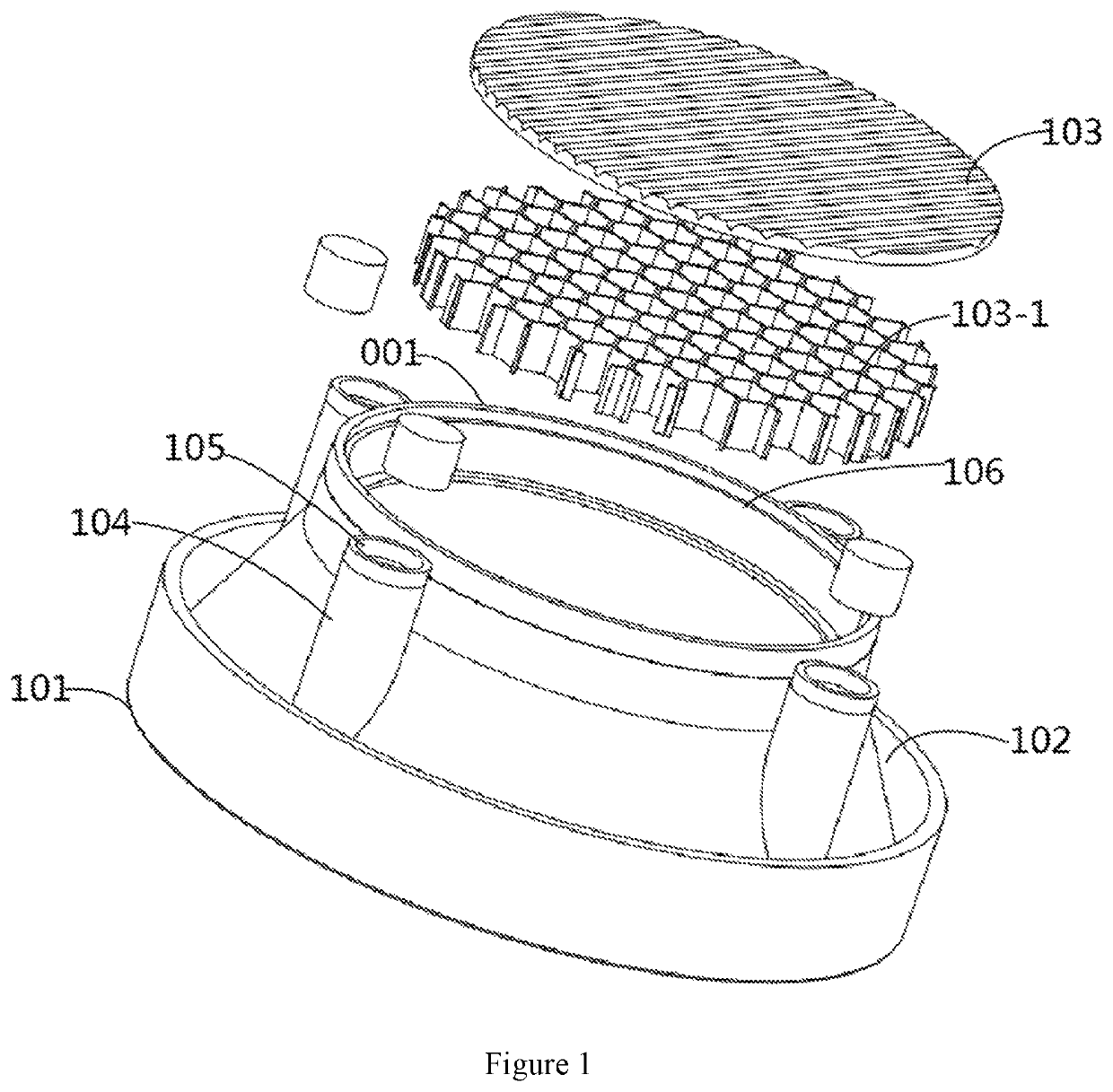
Magnetic module for light fixtures
a technology of magnetic module and led fixture, which is applied in the direction of refractors, lighting and heating devices, lighting support devices, etc., can solve the problems of hard and complex assembly of led fixture, and achieve the effect of improving assembly and replacement efficiency
- Summary
- Abstract
- Description
- Claims
- Application Information
AI Technical Summary
Benefits of technology
Problems solved by technology
Method used
Image


Examples
Embodiment Construction
[0026]In the following description, numerous specific details are set forth in order to provide a more thorough description of the present invention. It will be apparent, however, to one skilled in the art, that the present invention may be practiced without these specific details. In other instances, well-known features have not been described in detail so as not to obscure the invention.
[0027]The description through the words and drawings of this application are for the explanation of the present invention, rather than a limitation of the innovations herein. The words “center,”“longitudinal,”“transverse,”“length,”“width,”“thickness,”“up,”“down,”“forward,”“back,”“left,”“right,”“vertical,”“horizontal,”“top,”“bottom,”“inside,”“outside,”“clockwise,” and “counterclockwise” are for purposes of explanation, rather than limiting the associated devices and components to a specific position or direction and operation by a specific position or direction. Therefore, these words cannot be real...
PUM
| Property | Measurement | Unit |
|---|---|---|
| magnetic attraction | aaaaa | aaaaa |
| magnetic | aaaaa | aaaaa |
| energy | aaaaa | aaaaa |
Abstract
Description
Claims
Application Information