Magnetic-inductive flowmeter and corresponding method

a flowmeter and magnetic inductive technology, applied in the direction of electromagnetic flowmeters, instruments, volume/mass flow by electromagnetic flowmeters, etc., can solve the problem of allowing for imprecise measurement of flow speed, and achieve the effect of precise measurement of flow speed

Active Publication Date: 2020-06-02
KROHNE MESSTECHNICK GMBH & CO KG
View PDF11 Cites 0 Cited by
  • Summary
  • Abstract
  • Description
  • Claims
  • Application Information

AI Technical Summary

Benefits of technology

[0007]Based on the above-described prior art, a primary object of the present invention is to provide a magnetic-inductive flowmeter and a method for it that allows for a more exact measurement of the speed of flow compared to the prior art.
[0010]According to a preferred design of the invention, it is provided that the first and the second coil of the at least one coil pair are arranged radial to the axial direction of the measuring tube and perpendicular to a direction of flow at the circumferential wall of the measuring tube. Additionally or alternatively, this can also hold true for the at least one measuring electrode. This electrode can also be arranged radial to the axial direction of the measuring tube and, thus, at or with its electrode head perpendicular to the direction of flow at the circumferential wall of the measuring tube. A particularly homogeneous magnetic field can be generated by the arrangement of coils according to the invention. The magnetic field can be positioned using the arrangement according to the invention in such a manner that the electrode head or the longitudinal axis through the measuring electrode is arranged perpendicular to the magnetic field and thus perpendicular to the direction of flow of the measuring fluid. This allows for a particularly exact measurement of the speed of flow.
[0015]This effect is enhanced in that all coils or only respectively the first and the second coil of each coil pair are constructed identically to one another in respect to their characteristics such as geometry and / or winding number and / or winding cross section and / or production material.
[0017]The first coils of the at least n coil pairs are thereby arranged in a first coil plane that runs perpendicular through the measuring tube. The second coils of the at least n coil pairs are arranged in a second coil plane that also runs perpendicular through the measuring tube. The same holds true for the at least m measuring electrodes. They are arranged in a measuring plane that runs perpendicular through the measuring tube. The first coil plane, the second coil plane and the measuring plane are spaced from one another in the axial direction and parallel to one another. This accomplishes a particularly symmetrical construction, which positively affects the measuring accuracy of the magnetic-inductive flowmeter.
[0025]The method according to an embodiment of the invention is used for determining an axial flow speed distribution for a magnetic-inductive flowmeter. This operates using the DAR method. A weighting function is used in the DAR method. According to the invention, an iterative method is implemented in this weighting function. This allows for deviations between a reconstructed flow speed distribution and a provided flow speed distribution to be decreased.

Problems solved by technology

A disadvantage of the known measuring unit is that it only allows for imprecise measurement of the speed of flow, in particular in speed distribution that is not rotation symmetrical.

Method used


Image

  • Magnetic-inductive flowmeter and corresponding method
  • Magnetic-inductive flowmeter and corresponding method
  • Magnetic-inductive flowmeter and corresponding method

Examples


Embodiment Construction

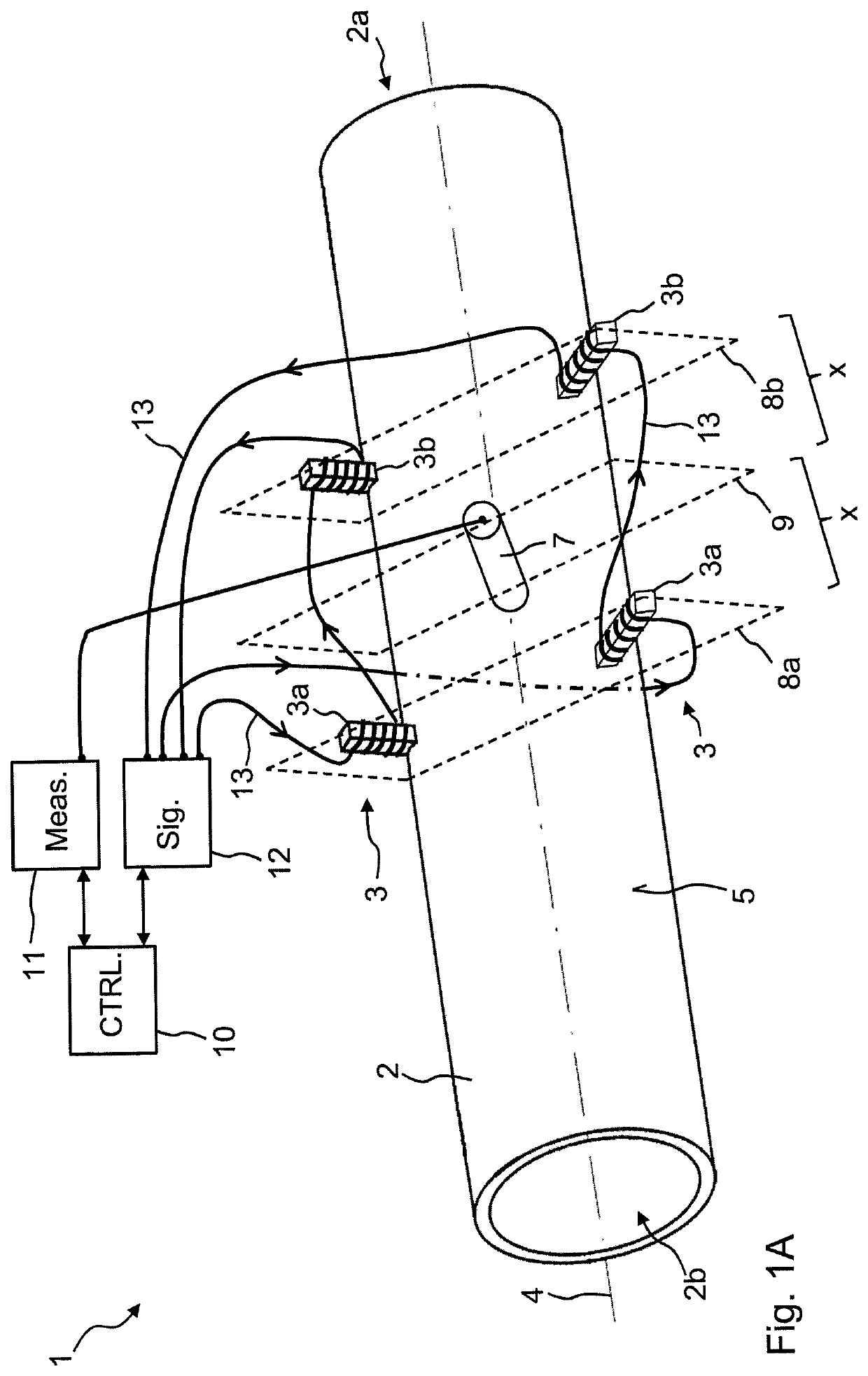
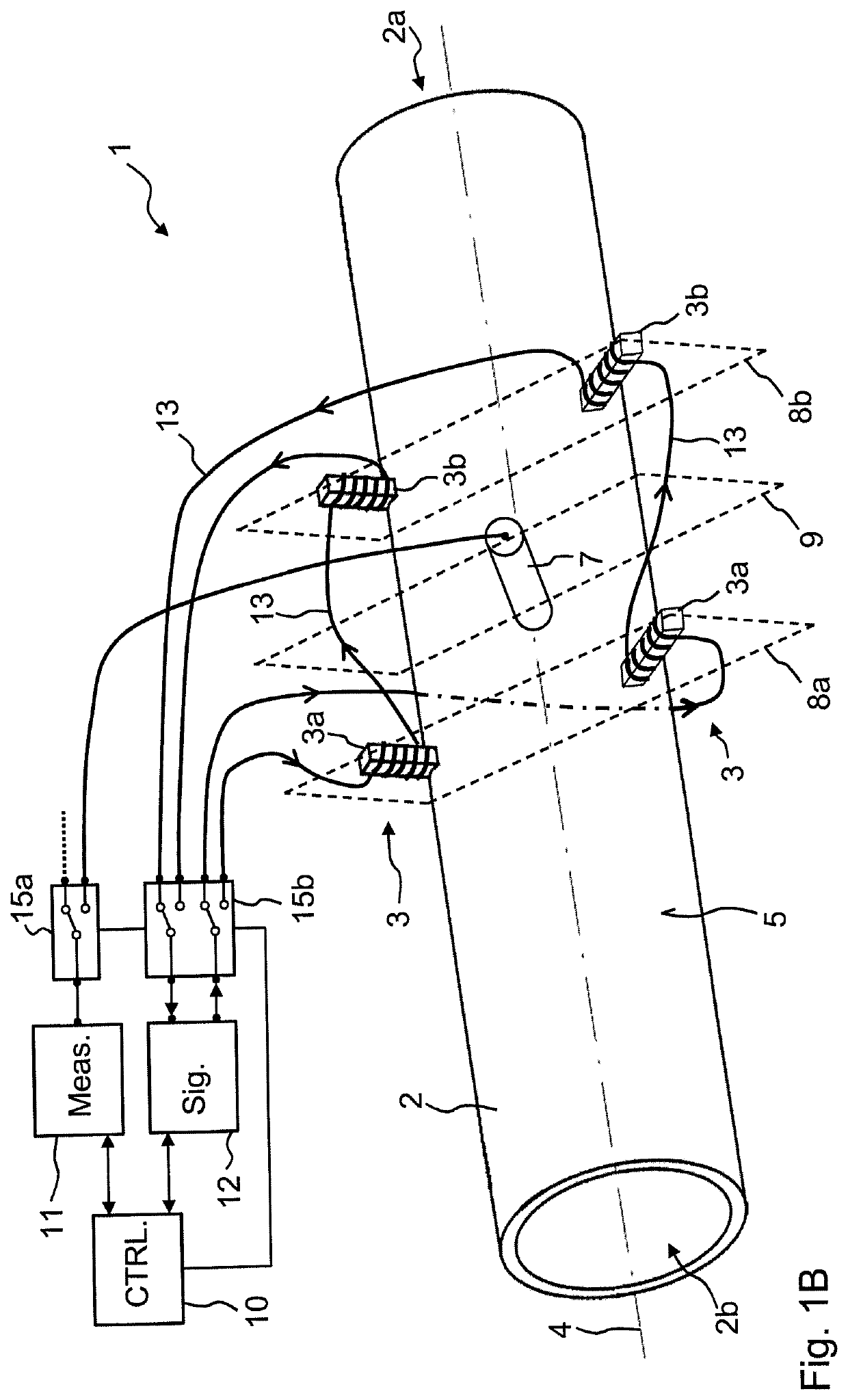
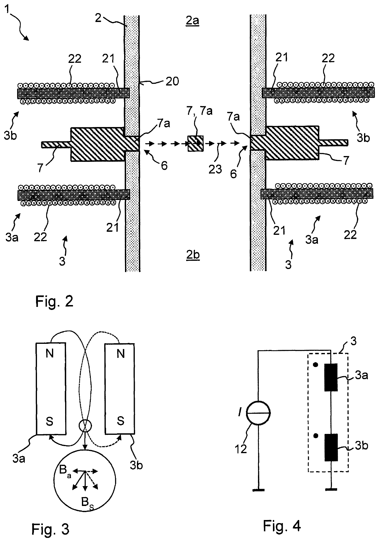
[0037]FIG. 1 shows a first embodiment of a magnetic-inductive flowmeter 1 according to the invention having a measuring tube 2 and two coil pairs 3 and at least one measuring electrode 7. The measuring tube 2 has an inflow section 2a and outflow section 2b, which are spaced from one another in the axial direction 4 of the measuring tube 2. An axis is shown in FIG. 1A, which runs in the axial direction 4 of the measuring tube 2. The measuring tube 2 has at least one opening 6 (shown in FIG. 2) on its circumferential wall 5, into which the at least one measuring electrode 7 joins or is arranged with its electrode head 7a (shown in FIG. 2).

[0038]The at least one coil pair 3 comprises a first coil 3a and a second coil 3b. Both the first coil 3a as well as the second coil 3b of the at least one coil pair 3 are arranged offset to one another in the axial direction 4 of the measuring tube 2 on the circumferential wall 5 of the measuring tube 2. The first and the second coil 3a, 3b are pref...


PUM


Abstract

A magnetic-inductive flowmeter with a measuring tube and at least one measuring electrode has at least one opening in its circumferential wall, at least a electrode head of the at least one measuring electrode being arranged in the at least one opening. At least one coil pair has first and second coils that are arranged offset to one another on the circumferential wall of the measuring tube in the axial direction of the measuring tube. The first and second coils are arranged at least partially overlapping to one another in a top view of a cross section through the measuring tube. The at least one measuring electrode is arranged in a peripheral area of the circumferential wall of the measuring tube that is located between the first and the second coil of the at last one coil pair.

Description

BACKGROUND OF THE INVENTION[0001]Field of the Invention[0002]The present invention relates to a magnetic-inductive flowmeter (MID) with a measuring tube and at least one measuring electrode, wherein the measuring tube comprises an inflow section and an outflow section, which are spaced to one another in an axial direction of the measuring tube. The measuring tube has at least one opening on its circumferential wall, in which at least one measuring electrode with its electrode head is arranged. A magnetic field is generated via a coil arrangement, which permeates the inside of the measuring tube. Furthermore, the invention relates to a method for such a magnetic-inductive flowmeter.[0003]Description of Related Art[0004]The measuring principle of magnetic-inductive flowmeters is based on the separation of moving charges in a magnetic field. The meteorological basis is formed by a measuring tube of a non-magnetic material, for example, of a non-magnetic metal or of plastic, which is el...

Claims


Application Information

Patent Timeline
Patent Type & Authority Patents(United States)
IPC IPC(8): G01F1/58
CPCG01F1/588G01F1/60G01F1/586
Inventor ABROLAT, JANMUSCH, THOMAS
Owner KROHNE MESSTECHNICK GMBH & CO KG
Why Eureka
Try Eureka