System and method for malware analysis using thread-level event monitoring

a technology of event monitoring and system and method, applied in the field of data security, can solve the problems of complex targeted process, difficult subsequent analysis of the process in efforts to determine which activities, if any, are potentially malicious, and the whole process is determined to be tainted and identified as potentially malicious

Active Publication Date: 2020-06-02
FIREEYE SECURITY HLDG US LLC
View PDF559 Cites 28 Cited by
  • Summary
  • Abstract
  • Description
  • Claims
  • Application Information

AI Technical Summary

Problems solved by technology

Upon detecting an anomalous event associated with one or more of these activities, the whole process is determined to be tainted and is identified as being potentially malicious.
Subsequent analysis of the process in efforts to determine which activities, if any, are malicious may be quite difficult, especially where the process performs thousands of activities and produces hundreds of anomalous events.
Such targeted processes are often computationally intensive as these processes may perform thousands of activities per second, where hundreds of events may be considered to be an

Method used


Image

  • System and method for malware analysis using thread-level event monitoring
  • System and method for malware analysis using thread-level event monitoring
  • System and method for malware analysis using thread-level event monitoring

Examples


second embodiment

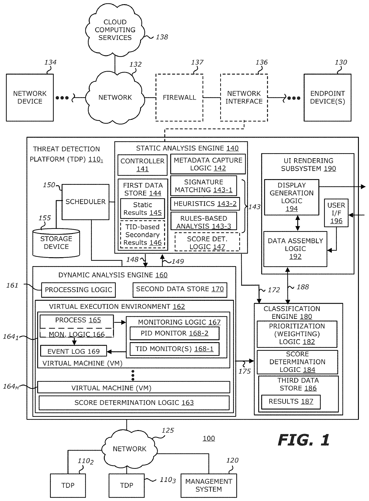
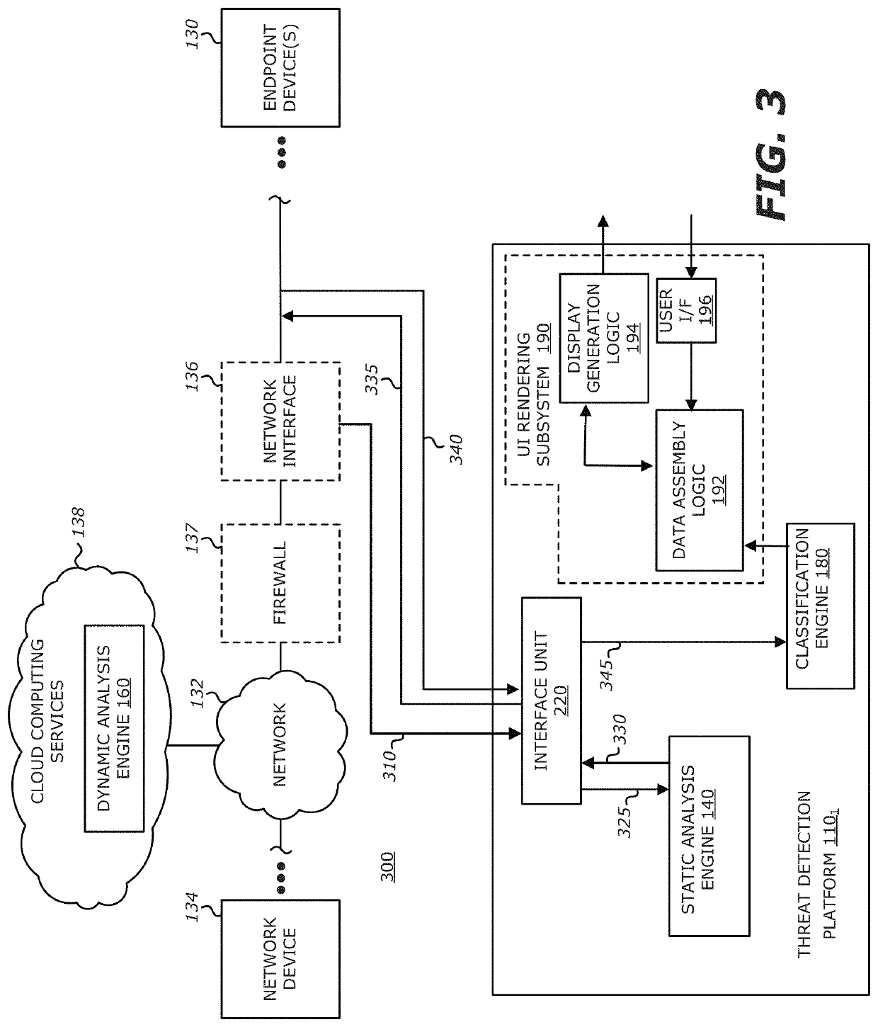
[0072]Referring now to FIG. 3, a block diagram of an exemplary network adapted with another configuration for the first TDP 1101 is shown. According to one embodiment of the disclosure, the first TDP 1101 may be communicatively coupled in-line with the endpoint device(s) 130. As shown, the first TDP 1101 may be communicatively coupled with the network 132 via an interface unit 320, which directs signaling 310 on communication network 132 to static analysis engine 140 and / or classification engine 180, given that the dynamic analysis engine 160 may be deployed in cloud computing services 138 as shown. Hence, one or more objects along with metadata in the network traffic are routed to the static analysis engine 140 via communication path 325. The suspicious objects may be routed via communication paths 330 and 335 to the dynamic analysis engine 160 in cloud computing services 138. Similarly, objects that are not determined to be at least “suspicious” may be returned for continued routi...

first embodiment

[0089]As shown in FIG. 10, a display representation 1000 of the inter-relationship between processes, threads, events and tasks in accordance with a tree-like, hierarchical topology is shown. Herein, the PIDs 10101-1010K (K≥1) and / or TIDs 1020-1027 are illustrated with one type of geometric shape for its display elements (e.g., oblong element) while the events 1030-1036, 1040-1042 and 1050-1051 are represented with another type of geometric shape for its display element (e.g., parallelogram). The relationship between the PIDs 10101-1010K, TIDs 1020-1027 and events 1030-1036, 1040-1042 and 1050-1051 are displayed through connection lines there between. When heuristics identifies a created thread or an activity on a thread to be suspicious, that thread and / or activity may be highlighted as shown by highlighted regions 1060 and 1070, which are represented by a different colors or shading along with its identified task 1065 and 1075, respectively.

[0090]More specifically, as shown in FIG...


PUM


Abstract

According to one embodiment, a computerized method comprises processing one or more objects by a first thread of execution that are part of a multi-thread process, monitoring events that occur during the processing of the one or more objects by the first thread, and storing information associated with the monitored events within an event log. The stored information comprises at least an identifier of the first thread to maintain an association between the monitored events and the first thread. Subsequently, the stored information within the event log is accessed for rendering a graphical display of the monitored events detected during processing of the one or more objects by the first thread on a display screen.

Description

1. FIELD[0001]Embodiments of the disclosure relate to the field of data security. More specifically, embodiments of the disclosure relate to a system and method for conducting malware analysis of objects using thread-level event monitoring, where the analysis results are used to generate one or more displays that identify relationships between threads of a multi-thread process and the events associated with each particular thread.2. GENERAL BACKGROUND[0002]Currently, some conventional malware detection systems are configured to monitor activities associated with a process. Upon detecting an anomalous event associated with one or more of these activities, the whole process is determined to be tainted and is identified as being potentially malicious. Subsequent analysis of the process in efforts to determine which activities, if any, are malicious may be quite difficult, especially where the process performs thousands of activities and produces hundreds of anomalous events.[0003]For i...

Claims


Application Information

Patent Timeline
IPC IPC(8): G06F21/00G06F21/56H04L29/06
CPCG06F21/562H04L63/1416G06F21/552G06F21/561G06F21/564G06F21/566
Inventor PAITHANE, SUSHANTVINCENT, MICHAELVASHISHT, SAI
Owner FIREEYE SECURITY HLDG US LLC
Why Eureka
Try Eureka