Liquid container

a liquid container and liquid technology, applied in printing, other printing apparatus, etc., can solve the problems of increasing concentration, affecting the quality of liquid, and blocking the channel in the bag,

Active Publication Date: 2020-06-09
SEIKO EPSON CORP
View PDF11 Cites 4 Cited by
  • Summary
  • Abstract
  • Description
  • Claims
  • Application Information

AI Technical Summary

Benefits of technology

[0007]According to the liquid container of this mode, a channel of liquid is secured due to a space in the periphery of the liquid outlet tube provided in the liquid storage portion, and the channel in the bag is unlikely to be blocked. In addition, the liquid outlet tube extends from the liquid outlet member toward the spacer member, and the spacer member is positioned on the farther side (the +D direction side) relative to the end portion on the +D direction side of the liquid outlet tube. Therefore, the end portion on the +D direction side of the liquid outlet tube and also a channel on the farther side of the end portion on the +D direction side are unlikely to be blocked. Moreover, liquid at a position separated from the spacer member can be guided toward the spacer member and be directed to the liquid outlet tube, using at least one directing channel that extends from an edge portion side of the liquid storage portion in a direction approaching the spacer member, and directs liquid toward the spacer member. Therefore, it is possible to suppress inhibition of flow of liquid in the bag, and liquid and sedimentary components can be kept from remaining in the liquid container. In particular, disruption of flow of liquid at a position separated from the spacer member is suppressed due to the directing channel, and thus it is possible to smoothly direct sedimentary components as well as liquid toward the liquid outlet tube, and sedimentary components are kept from remaining. Therefore, according to the liquid container of this mode, it is possible to sufficiently supply liquid to the liquid ejection apparatus. In addition, it is possible to improve the evenness of the concentration of liquid that is supplied to liquid ejection apparatus.
[0031]According to the liquid container of this mode, the positional relationship between the spacer member and the liquid outlet member can be further stabilized.

Problems solved by technology

However, depending on the position at which the shrinkage occurs and the state of the shrinkage, there is a possibility that a channel in the bag is blocked, and liquid cannot be sufficiently supplied to the liquid ejection apparatus.
Therefore, at an initial state of liquid consumption, the liquid that contains a small amount of sedimentary components with a low concentration is discharged, and as the liquid is further consumed, the rate of the sedimentary components that retain in the bag increases, thereby the concentration increases, and there has been a risk that the concentration of the sedimentary components in the liquid that is supplied to the liquid ejection apparatus becomes uneven.
In particular, in a section that is far from a liquid supply port that is connected to the liquid ejection apparatus, there is a tendency that a channel is likely to be blocked and flow of liquid is likely to stop, and there is a tendency that liquid and sedimentary components are likely to retain.
Such tendencies exist regardless of the volume of the bag, and, in particular, there has been a possibility that such tendencies are significant if the volume of the bag is large.

Method used


Image

  • Liquid container
  • Liquid container
  • Liquid container

Examples


first embodiment

1. First Embodiment

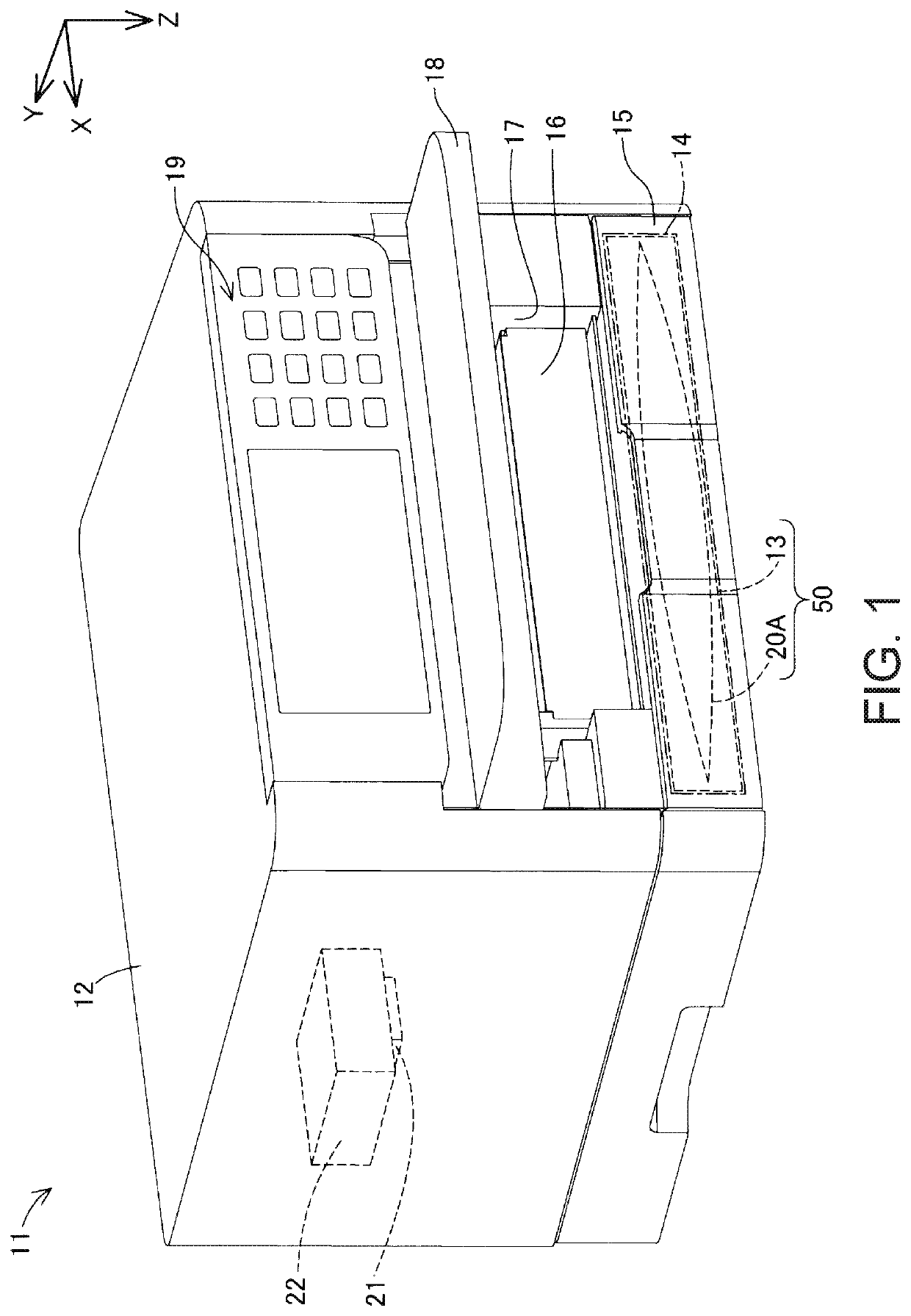
[0054]FIG. 1 is a schematic perspective view of a liquid ejection apparatus 11 in which a liquid container 20A in a first embodiment is stored. In FIG. 1, an X axis, a Y axis, and a Z axis indicating three directions orthogonal to each other are illustrated. The X axis and the Y axis indicate directions parallel to a horizontal plane. The X axis is parallel to the width direction of the liquid ejection apparatus 11 in a normal usage orientation in which the liquid ejection apparatus 11 is arranged on a horizontal plane, and indicates a direction from the right to the left when opposed to the front face of the liquid ejection apparatus 11 (to be described later). The Y axis is parallel to the front-rear direction of the liquid ejection apparatus 11 in the normal usage orientation, and indicates a direction from the front face toward the rear face of the liquid ejection apparatus 11. In the present specification, the Y axis direction may be referred to as “depth dir...

second embodiment

2. Second Embodiment

[0172]The configuration of directing channels 101 of a liquid container 20B in a second embodiment will be described with reference to FIG. 18. FIG. 18 is a schematic plane view of a bag unit 60u provided in the liquid container 20B of the second embodiment when viewed in the −T direction. In FIG. 18, as a matter of convenience, the entire liquid outlet unit LU is illustrated to be visible through the bag 60. The liquid container 20B of the second embodiment has substantially the same configuration as the configuration of the liquid container 20A of the first embodiment except that a third inclined channel 101d and a fourth inclined channel 101e are added as the directing channels 101 that are formed by a channel formation portion 100.

[0173]In the second embodiment, the channel formation portion 100 is configured to form five directing channels 101 extending from an end portion side of a liquid storage portion 60c in a direction approaching a spacer member 90. th...

third embodiment

3. Third Embodiment

[0179]The configuration of directing channels 101 of a liquid container 20C in a third embodiment will be described with reference to FIG. 19. FIG. 19 is a schematic plane view of a bag unit 60u provided in the liquid container 20C of the third embodiment when viewed in the −T direction. In FIG. 19, as a matter of convenience, the entire liquid outlet unit LU is illustrated to be visible through a bag 60. The liquid container 20C of the third embodiment has substantially the same as the configuration of the liquid container 20A of the first embodiment, except that a plurality of parallel channels 101f are formed as the directing channels 101 formed by the channel formation portion 100 in place of the three channels 101a to 101c.

[0180]In the third embodiment, the channel formation portion 100 is configured to form a plurality of parallel channels 101f as the directing channels 101 extending from end portion sides of the liquid storage portion 60c in a direction ap...


PUM


Abstract

Liquid and sedimentary components are kept from remaining in a bag of a liquid container. The liquid container includes a flexible bag in which a liquid storage portion for containing a liquid is provided, a liquid outlet member that is attached to one edge portion of the bag, and has a liquid outlet portion for leading out the liquid to a liquid ejection apparatus, a spacer member arranged in the liquid storage portion, and a liquid outlet tube that constitutes a flow path of liquid extending in the liquid storage portion from the liquid outlet member toward the spacer member. The spacer member is arranged at a position separated from an end portion of the liquid storage portion, and at least one directing channel extending from the end portion side of the liquid storage portion in a direction approaching the spacer member is formed in the liquid storage portion.

Description

BACKGROUND1. Technical Field[0001]The present invention relates to a liquid container.2. Related Art[0002]Heretofore, liquid storage bodies for supplying liquid to a liquid ejection apparatus have been widely used. For example, liquid storage bodies disclosed in JP-A-2009-34989, Japanese Patent No. 4519070, JP-A-2015-168247 and JP-A-2008-87486 have a flexible bag, which contains a liquid to be supplied to a liquid ejection apparatus.[0003]JP-A-2009-34989, Japanese Patent No. 4519070, JP-A-2015-168247 and JP-A-2008-87486 are examples of related art.[0004]The flexible bag shrinks as the liquid is consumed. However, depending on the position at which the shrinkage occurs and the state of the shrinkage, there is a possibility that a channel in the bag is blocked, and liquid cannot be sufficiently supplied to the liquid ejection apparatus. In addition, sedimentary components contained in the liquid are likely to retain. Therefore, at an initial state of liquid consumption, the liquid tha...

Claims


Application Information

Patent Timeline
Patent Type & Authority Patents(United States)
IPC IPC(8): B41J2/175B41J29/13
CPCB41J2/17553B41J2/17523B41J2/17513B41J2/175B41J2/1752B41J2/17556B41J2/1753B41J29/13B41J2002/17516
Inventor NAGASHIMA, TAKUMIKAWATE, HIROYUKIOZEKI, HIROYUSHIYAMAGUCHI, MANABU
Owner SEIKO EPSON CORP
Why Eureka
Try Eureka