Eureka AIR delivers breakthrough ideas for toughest innovation challenges, trusted by R&D personnel around the world.

Deployable wing for an aircraft

Active Publication Date: 2020-06-09
NORTHROP GRUMMAN SYST CORP
View PDF9 Cites 3 Cited by
  • Summary
  • Abstract
  • Description
  • Claims
  • Application Information

AI Technical Summary

Benefits of technology

[0003]In an embodiment, an apparatus for selectively increasing a wing area of an aircraft having a fuselage with an interior space is provided. The apparatus includes an inflatable wing moveable between a stowed condition located in the interior space and a deployed condition located outside the interior space. The wing includes at least one inflatable spar. The inflatable spar is operatively coupled to a source of pressurized inflation fluid for selective inflation as the wing moves into the deployed condition. A plurality of reels is secured to the aircraft. A plurality of cables connects the wing to the reels. The cables are spaced apart from one another in a fore-aft direction along the wing. At least one reel is operable to unwind a selected cable to allow the wing to partially inflate to the deployed condition by ram air generated by movement of the aircraft as the inflatable spar is being inflated by the pressurized inflation fluid to urge the wing toward the deployed condition.
[0004]In an embodiment, an aircraft is provided. An outer mold line is on a fuselage of the aircraft. An interior space is within the fuselage. An inflatable wing is moveable between a stowed condition, wherein the wing is substantially contained within the interior space and a deployed condition, wherein the inflatable wing is located substantially outside the outer mold line, in the ambient space. The inflatable wing includes substantially planar flexible upper and lower wing panels being attached together at an aft edge thereof and including space therebetween, when the wing is in the deployed condition, to form a wing interior. The wing interior is configured to accept, and thus become inflated by, ram air flow. At least one inflatable spar is operatively coupled to a source of pressurized inflation fluid for selective inflation as the wing moves int

Problems solved by technology

Current state-of-the-art high-speed aircraft may have difficulty operating at low speed, such as for takeoff, landing, and loitering.
However, there are many

Method used


Image

  • Deployable wing for an aircraft
  • Deployable wing for an aircraft
  • Deployable wing for an aircraft

Examples


Example

[0022]This technology comprises, consists of, or consists essentially of the following features, in any combination.

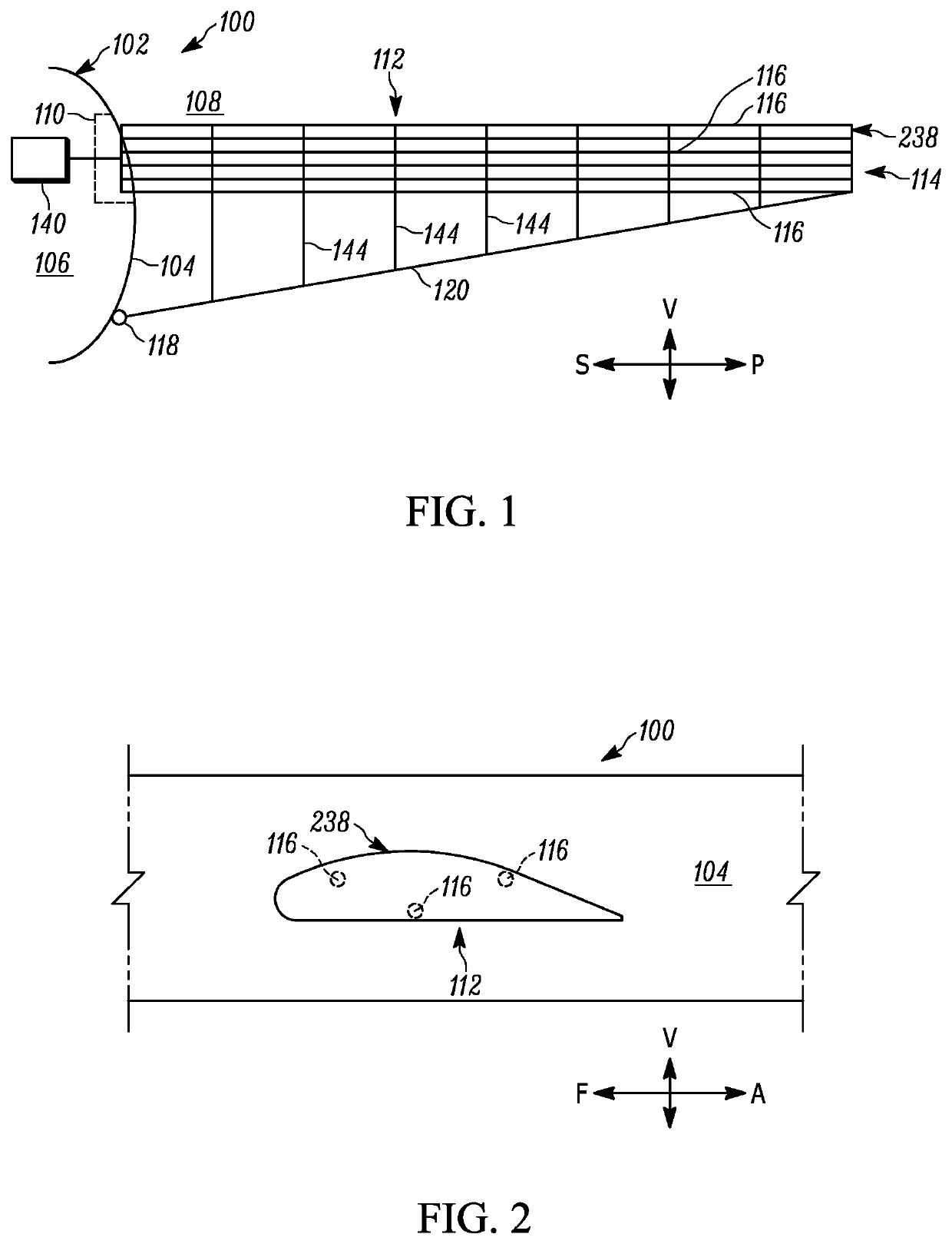
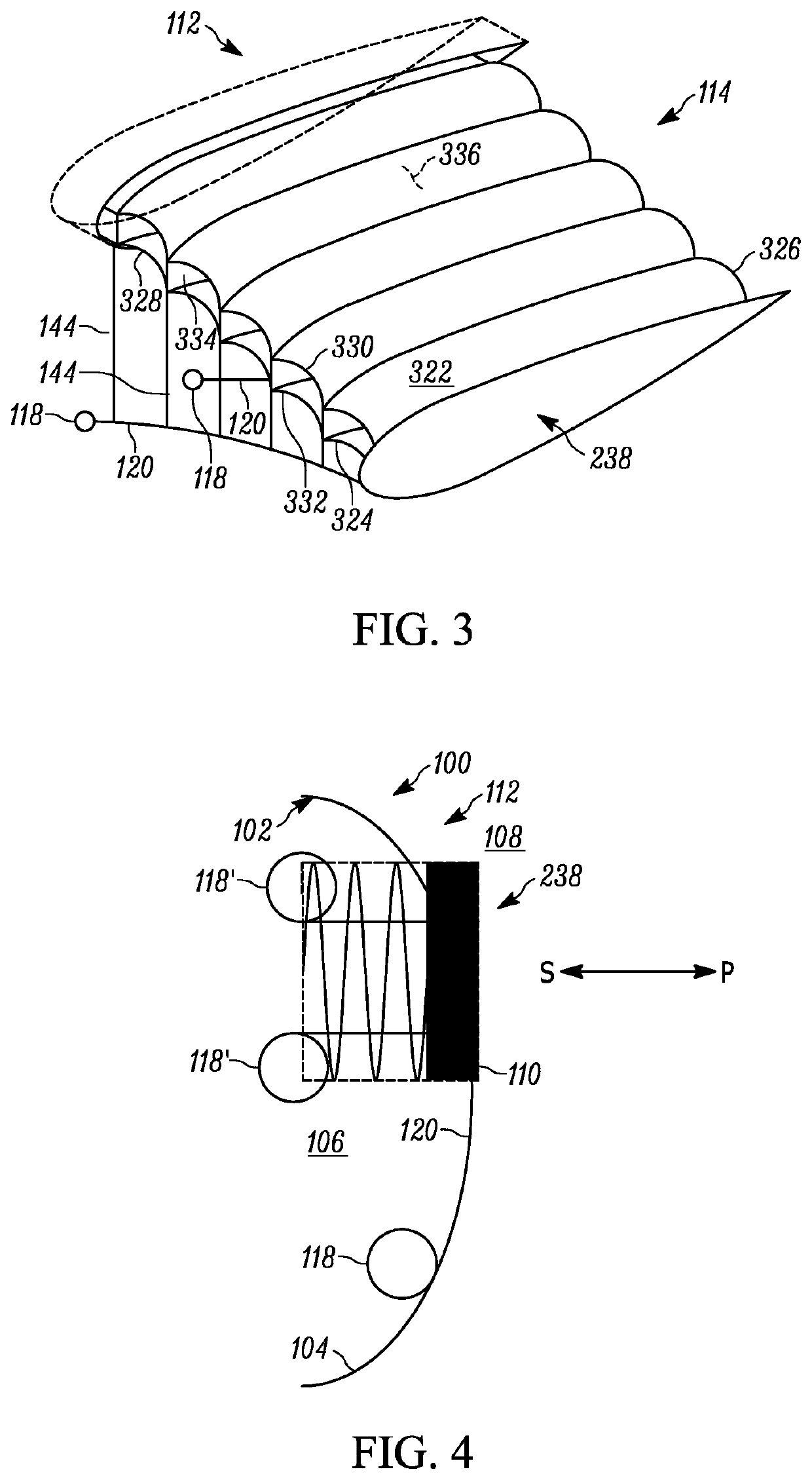
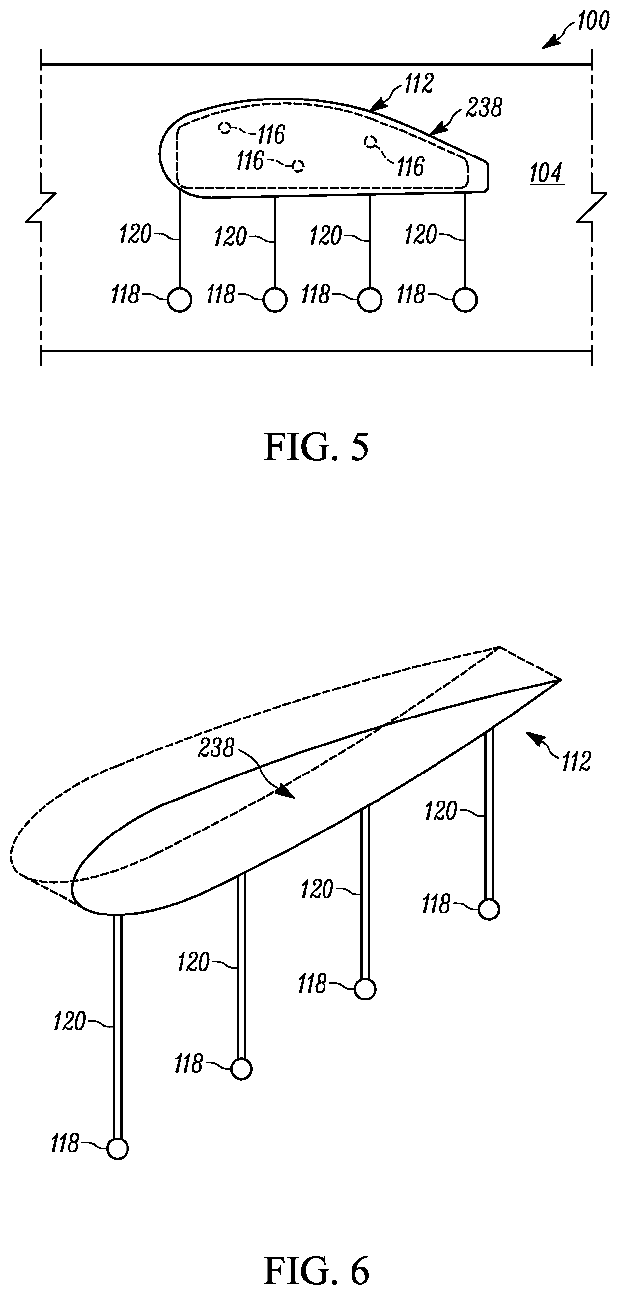
[0023]FIG. 1 schematically depicts a portion of an aircraft 100. A fuselage 102 of the aircraft 100 has an outer mold line 104. An interior space 106 of the aircraft 100 may be separated from ambient space 108 by an aperture 110 in the outer mold line 104. An apparatus 112 is provided for selectively increasing a wing area of the aircraft 100. The apparatus 112 includes an inflatable wing 114 selectively moveable between a stowed condition (shown in FIG. 4) where the wing 114 is located in the interior space 106 and a deployed condition (shown in FIG. 1) where the wing 114 is located outside the interior space 106. For example, the wing 114 could be substantially contained within the interior space 106 in the stowed condition and located wholly outside the outer mold line 104, in the ambient space 108, in the deployed condition. While a fuselage 102 is used herein as a...


PUM


Abstract

An apparatus for selectively increasing a wing area of an aircraft having a fuselage with an interior space includes an inflatable wing moveable between a stowed condition located in the interior space and a deployed condition located outside the interior space. The wing includes at least one inflatable spar. The inflatable spar is operatively coupled to a source of pressurized inflation fluid for selective inflation as the wing moves into the deployed condition. A plurality of reels is secured to the aircraft. A plurality of cables connects the wing to the reels. At least one reel is operable to unwind a selected cable to allow the wing to partially inflate to the deployed condition by ram air generated by movement of the aircraft as the inflatable spar is being inflated by the pressurized inflation fluid. A method for selectively increasing a wing area of an aircraft is also provided.

Description

TECHNICAL FIELD[0001]This disclosure relates to an apparatus and method for use of a deployable wing for an aircraft and, more particularly, to a method and apparatus for selectively increasing a wing area of an aircraft having a fuselage with an interior space.BACKGROUND[0002]Current state-of-the-art high-speed aircraft may have difficulty operating at low speed, such as for takeoff, landing, and loitering. Greater wing area would facilitate selective low-speed operation of normally high-speed aircraft. However, there are many design trade-offs, such as a significant weight increase, needed to provide a high-speed aircraft with increased wing area using current design principles.SUMMARY[0003]In an embodiment, an apparatus for selectively increasing a wing area of an aircraft having a fuselage with an interior space is provided. The apparatus includes an inflatable wing moveable between a stowed condition located in the interior space and a deployed condition located outside the int...

Claims


Application Information

Patent Timeline
IPC IPC(8): B64C3/38B64C3/18B64C3/54B64C3/56B64C3/30
CPCB64C3/187B64C3/56B64C3/54B64C3/30
Inventor KEAVNEY, THOMAS E.BAUER, ROBERT E.
Owner NORTHROP GRUMMAN SYST CORP
Why Eureka
Eureka Blog
Learn More