Vehicle based data collection and processing system and imaging sensor system and methods thereof

Active Publication Date: 2007-03-01
VI TECH LLC
View PDF46 Cites 198 Cited by
  • Summary
  • Abstract
  • Description
  • Claims
  • Application Information

AI Technical Summary

Benefits of technology

[0009] The system may also include an Attitude Measurement Unit (AMU) such as inertial, optical, or similar measurement units communicatively connected to the computer consoles and the camera array assemblies. The AMU may determine the yaw, pitch, and / or roll of the aircraft at any instant in time and successive DGPS positions may be used to measure the vehicle heading with relation to geodesic north. The AMU data is integrated with the precision DGPS data to produce a robust, real-time AMU system. The system may further include a mosaicing module housed within the computer consoles. The mosaicing module includes a first component for performing initial processing on an input image. The mosaicing module also includes a second component for determining geographical boundaries of an input image with the second component being cooperatively engaged with the first component. The mosaicing module further includes a third component for mapping an input image into the composite image with accurate geographical position. The third component being cooperatively engaged with the first and second components. A fourth component is also included in the mosaicing module for balancing color of the input images mapped into the composite image. The fourth component can be cooperatively engaged with the first, second and third components. Additionally, the mosaicing module can include a fifth component for blending borders between adjacent input images mapped into the composite image. The fifth component being cooperatively engaged with the first, second, third and fourth components.
[0010] A sixth component, an optional forward oblique and / or optional rear oblique camera array system may be implemented that collects oblique image data and merges the image data with attitude and positional measurements in order to create a digital elevation model using stereographic techniques. Creation of which may be performed in real-time onboard the vehicle or post processed later. This sixth component works cooperatively with the other components. All components may be mounted to a rigid platform for the purpose of providing co-registration of sensor data. Vibrations, turbulence, and other forces may act on the vehicle in such a way as to create errors in the alignment relationship between sensors. Utilization of common, rigid platform mount for the sensors provides a significant advantage over other systems that do not use this co-registration architecture.

Problems solved by technology

Vibrations, turbulence, and other forces may act on the vehicle in such a way as to create errors in the alignment relationship between sensors.

Method used


Image

  • Vehicle based data collection and processing system and imaging sensor system and methods thereof
  • Vehicle based data collection and processing system and imaging sensor system and methods thereof
  • Vehicle based data collection and processing system and imaging sensor system and methods thereof

Examples


Embodiment Construction

[0032] While the making and using of various embodiments of the present invention are discussed in detail below, it should be appreciated that the present invention provides many applicable inventive concepts, which can be embodied in a wide variety of specific contexts. The specific embodiments discussed herein are merely illustrative of specific ways to make and use the invention and do not limit the scope of the invention.

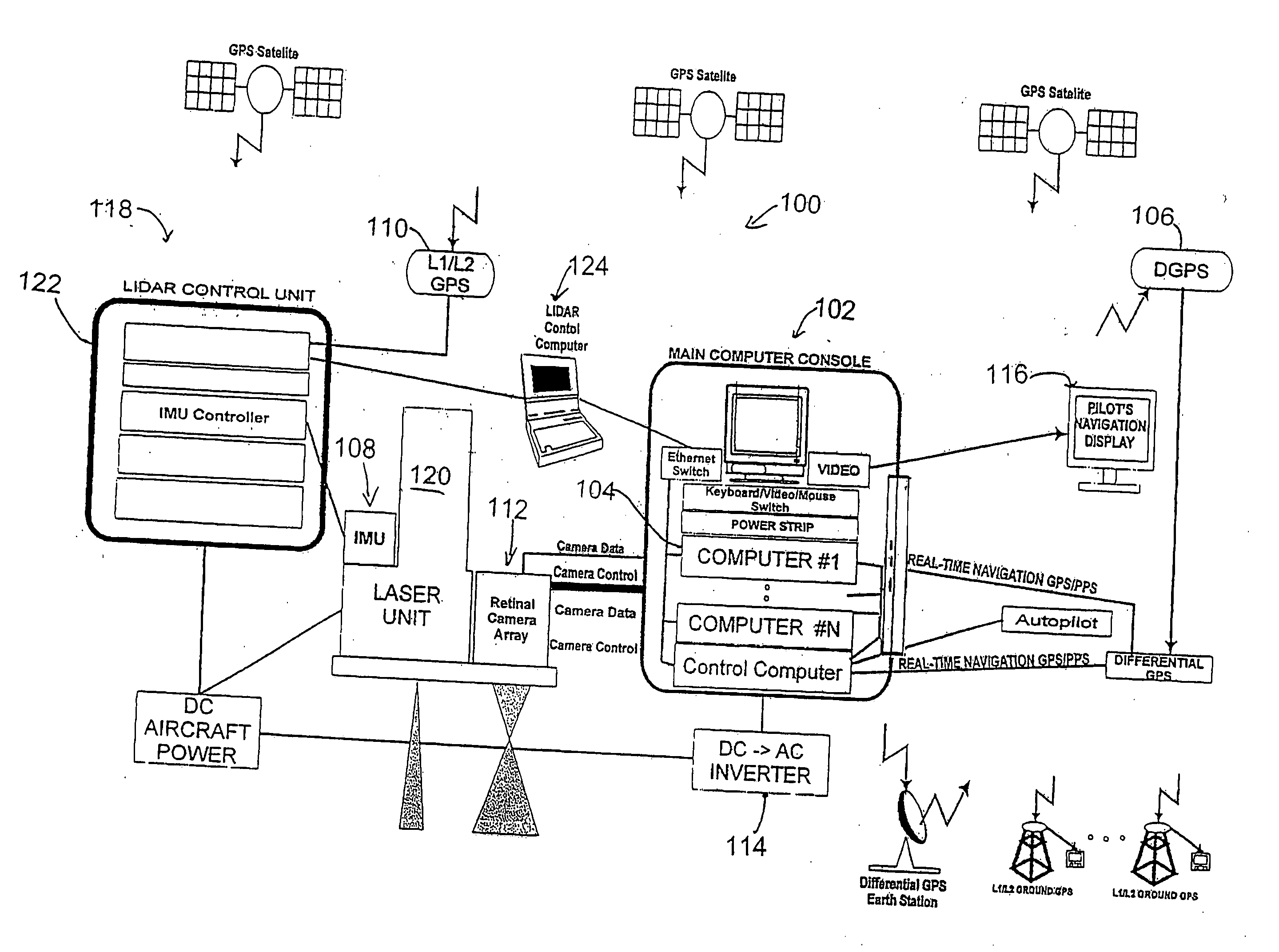
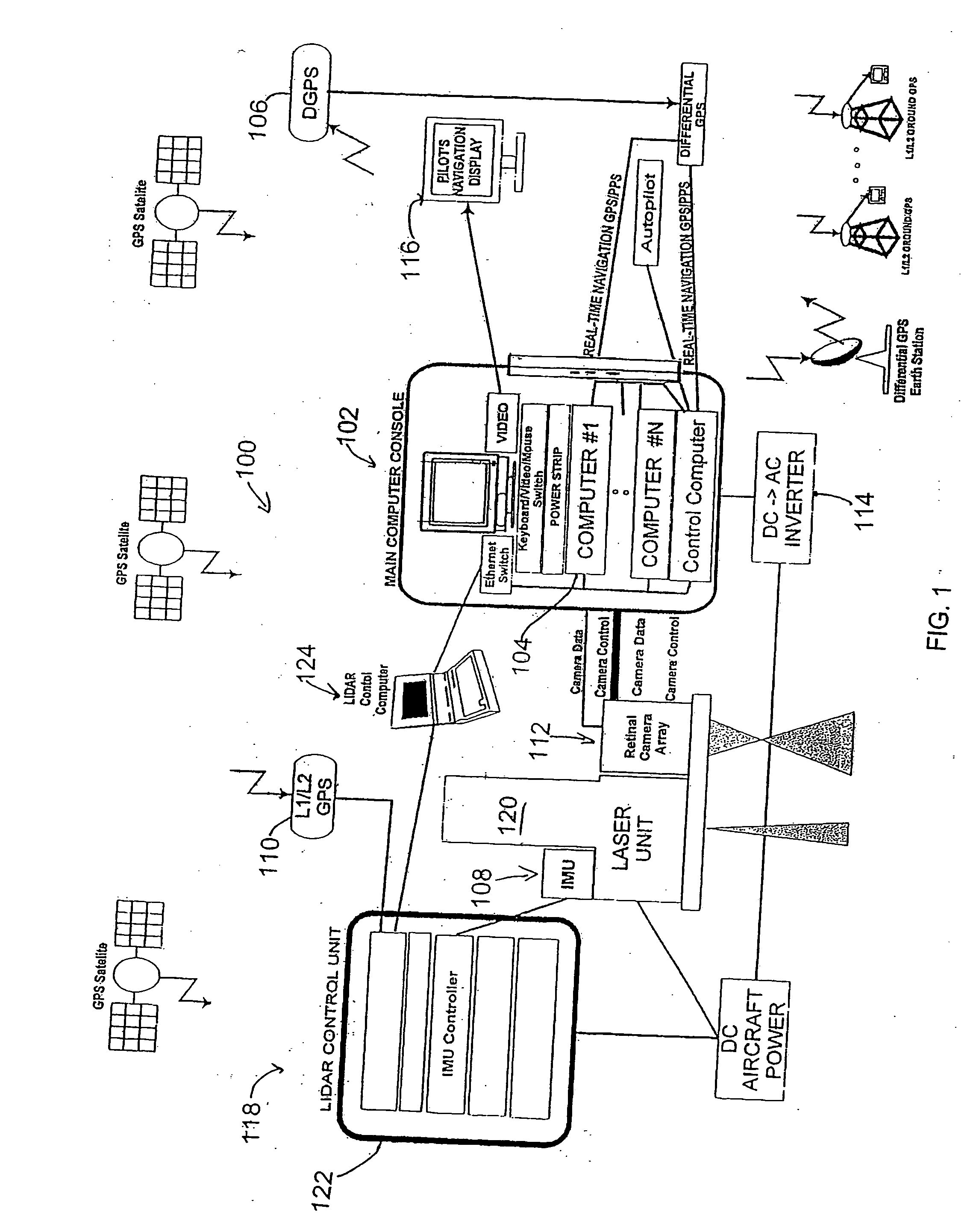
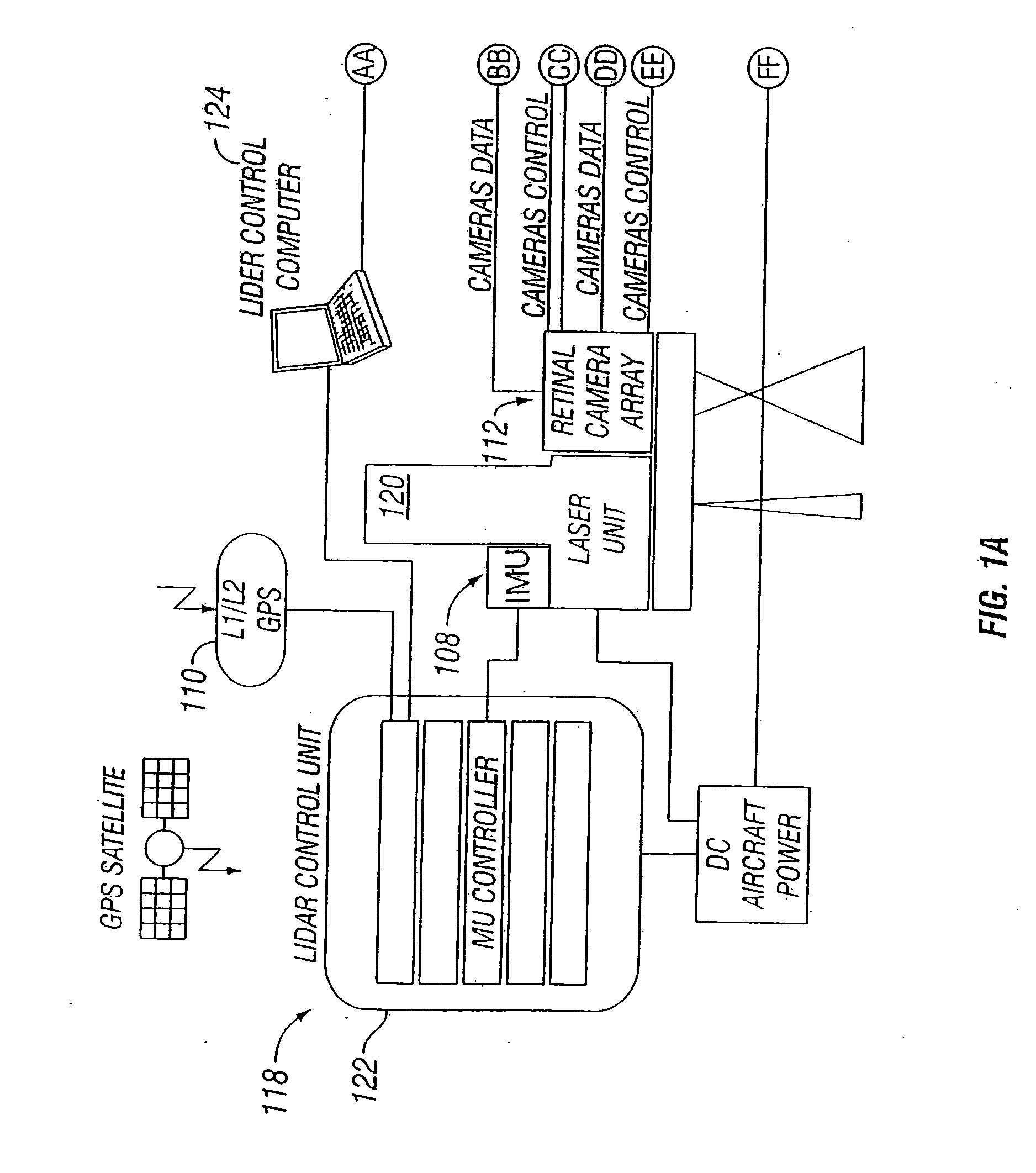
[0033] A vehicle based data collection and processing system 100 of the present invention is shown in FIGS. 1, 1A, and 1B. Additional aspects and embodiments of the present invention are shown in FIGS. 2 and 18. System 100 includes one or more computer consoles 102. The computer consoles contain one or more computers 104 for controlling both vehicle and system operations. Examples of the functions of the computer console are the controlling digital color sensor systems that can be associated with the data collection and processing system, providing the display ...


PUM


Abstract

A vehicle based data collection and processing system which may be used to collect various types of data from an aircraft in flight or from other moving vehicles, such as an automobile, a satellite, a train, etc. In various embodiments the system may include: computer console units for controlling vehicle and system operations, global positioning systems communicatively connected to the one or more computer consoles, camera array assemblies for producing an image of a target viewed through an aperture communicatively connected to the one or more computer consoles, attitude measurement units communicatively connected to the one or more computer consoles and the one or more camera array assemblies, and a mosaicing module housed within the one or more computer consoles for gathering raw data from the global positioning system, the attitude measurement unit, and the retinal camera array assembly, and processing the raw data into orthorectified images.

Description

CROSS-REFERENCE TO RELATED APPLICATION [0001] This application is a continuation-in-part of prior U.S. patent application Ser. No. 10 / 664,737, filed Sep. 18, 2003, which claimed priority to U.S. Provisional Patent Application Ser. No. 60 / 412,504 filed Sep. 20, 2002 for “Vehicle Based Data Collection and Processing System.”TECHNICAL FIELD OF THE INVENTION [0002] The present invention relates, generally, to the field of remote imaging techniques and, more particularly, to a system for rendering high-resolution, high accuracy, low distortion digital images over very large fields of view. BACKGROUND OF THE INVENTION [0003] Remote sensing and imaging are broad-based technologies having a number of diverse and extremely important practical applications—such as geological mapping and analysis, military surveillance and planning, and meteorological forecasting. Aerial and satellite-based photography and imaging are especially useful remote imaging techniques that have, over recent years, be...

Claims


Application Information

Patent Timeline
Patent Type & Authority Applications(United States)
IPC IPC(8): G08B21/00
CPCG01C11/02G03B37/04G01S19/14G01S17/88
Inventor SMITHERMAN, CHESTER L.
Owner VI TECH LLC
Why Eureka
Try Eureka