
Light fixture for an LED-based aircraft lighting system

a technology of led-based aircraft and light fixtures, which is applied in the direction of general lighting, mass transit vehicle lighting, lighting support devices, etc., can solve the problems of led deformation, inability to change the color of the light, and people constantly exposed to light,

Inactive Publication Date: 2007-04-03
BE AEROSPACE INCORPORATED
View PDF33 Cites 190 Cited by
  • Summary
  • Abstract
  • Description
  • Claims
  • Application Information

AI Technical Summary

Problems solved by technology

A problem associated with fluorescent lighting is that it can, over an extended period of time, become fatiguing to persons constantly exposed to the light.
Furthermore, while the light can be dimmed or brighten, the color of the light cannot be changed.
Otherwise, there is a risk that the semiconductor material of the LEDs will degrade quickly, thereby requiring frequent replacement of the LEDs.

Method used


Image

  • Light fixture for an LED-based aircraft lighting system
  • Light fixture for an LED-based aircraft lighting system
  • Light fixture for an LED-based aircraft lighting system

Examples


Embodiment Construction

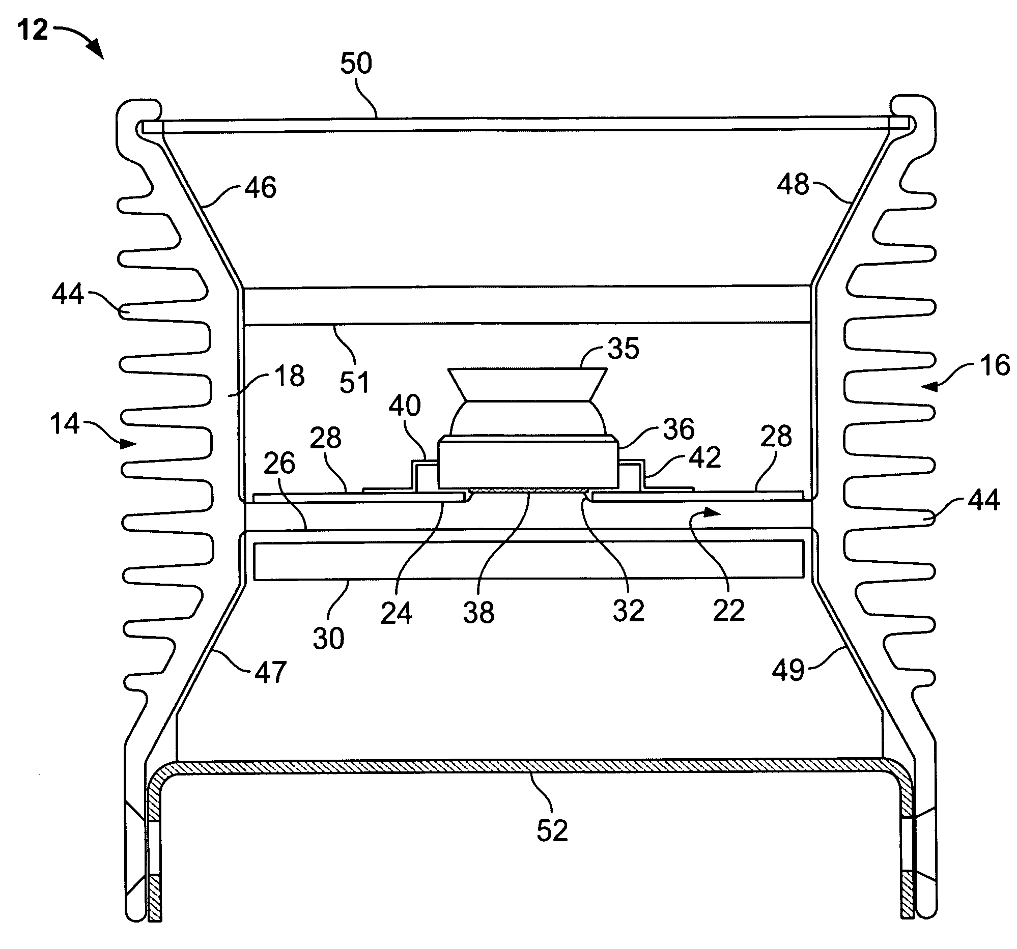
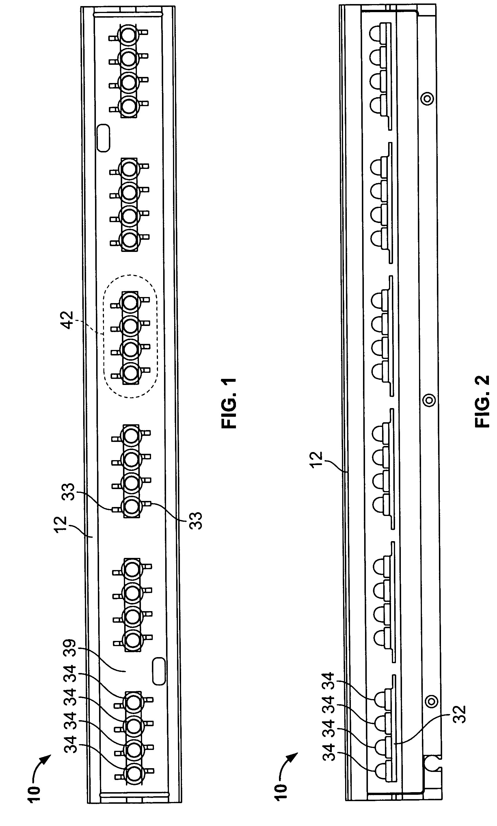
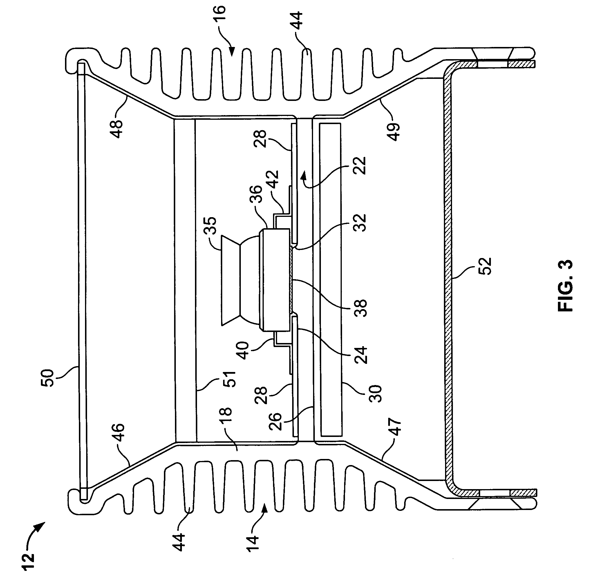
[0010]The invention is generally directed to a light fixture for use in an LED lighting system for an aircraft. Referring to FIGS. 1–3, an embodiment of the light fixture, generally labeled 10, includes a housing 12 having a first side 14 and a second side 16. The first and second sides 14 and 16 are displaced from one another. The first side 14 has an inner surface that has an angled upper portion 46, a substantially straight portion 18, and an angled lower portion 47. The second side 16 has an inner surface that has an angled upper portion 48, a substantially straight portion 20, and an angled lower portion 49. The length of the first side 14 is longer that the height of the first side 14. Similarly, the length of the second side 16 is longer that the height of the second side 16. A crossbar 22 is connected to the substantially straight portion 18 of the inner surface of the first side 14 at substantially at the mid-point of the height of the first side 14. The crossbar 22 is also...


PUM


Abstract

A light fixture for housing LED units is provided. The light fixture has a housing that has a substantially H-shaped cross section. The housing has a crossbar with a series of mesas defined on its upper surface. A group of LED units is attached to each of the series of mesas, each LED unit being attached with a thin layer of adhesive. The LED units are electrically insulated from the housing by either the adhesive, which may be electrically insulating, or by an electrically insulating coating on the housing.

Description

CROSS-REFERENCE TO RELATED APPLICATIONS[0001]The present application claims the benefit of the filing date of U.S. Provisional Application No. 60 / 530,492, filed Dec. 18, 2003, which is hereby incorporated by reference in its entirety.FIELD OF THE INVENTION[0002]This invention pertains to light fixtures and, more particularly, to light fixtures that use light-emitting diodes and structures or materials that dissipate heat generated by the light-emitting diodes.BACKGROUND OF THE INVENTION[0003]Lighting systems for aircraft interiors are well known. Conventional lighting systems include the use of fluorescent lights to brighten the inside of an aircraft cabin. Fluorescent light is used because it provides lighting sufficient to illuminate the cabin so as to provide an environment that allows passengers and cabin personnel to work and function comfortably. In addition to light intensity, other advantages of fluorescent light include the fact that it is energy efficient and highly reliab...

Claims


Application Information

Patent Timeline
Patent Type & Authority Patents(United States)
IPC IPC(8): F21V29/00F21S8/10F21V1/00F21V7/20F21V29/505
CPCB60Q3/025B60Q3/0259F21V15/01F21V29/004F21V29/767F21V23/006F21V29/75F21S4/003F21Y2103/003H05K1/0204F21Y2101/02F21S4/20F21Y2103/10F21Y2115/10B60Q3/43B60Q3/47
Inventor GLOISTEN, JENNIFER L.PAWELKO, TOLEK
Owner BE AEROSPACE INCORPORATED
Learn More