
Effector comprising a contact surface having an interface made of a ductile material

a technology of ductile material and contact surface, which is applied in the direction of gripping heads, metal-working machine components, manufacturing tools, etc., can solve the problems of insufficient first alternative form, inability to completely satisfy, and inability to produce acceptable machining marks, so as to reduce the risk of the contact surface of the effector slipping on the workpiece that is to be machined, and reduce the risk of the tool slipping risk , the effect of not impairing the integrity of the work

Active Publication Date: 2020-06-23
AIRBUS OPERATIONS (SAS)
View PDF28 Cites 0 Cited by
  • Summary
  • Abstract
  • Description
  • Claims
  • Application Information

AI Technical Summary

Benefits of technology

[0011]The ductile material affords good rigidity between the contact surface of the effector and the workpiece because the elastic modulus of the ductile material is markedly higher than that of elastomers. It also confers an adhesion coefficient that is markedly higher than that of a smooth contact surface, said adhesion coefficient limiting the risk of slippage of the tool on the face of the workpiece. Finally, it does not impair the integrity of the workpiece.

Problems solved by technology

If it does, and if the machine tool slips on the surface of the workpiece that is to be machined, it generates unacceptable machining marks.
However, this first alternative form is not entirely satisfactory because the contact surface of the effector has a low adhesion coefficient of the order of 0.2.
Thus, the risks of the contact surface of the effector slipping on the workpiece that is to be machined are not negligible.
However, this solution is not satisfactory because it reduces productivity.
However, it is not entirely satisfactory because it is not possible to ensure that the slight penetration of the fine particles of the contact surface of the effector will not impair the workpiece that is to be machined.
However, it is not entirely satisfactory because if the elastomer coating has a small thickness of the order of 0.01 mm, the risks of separation of the coating are high because of the shear stresses, and if the elastomer coating has a thickness greater than 0.01 mm it does not provide rigid contact between the contact surface of the effector and the workpiece that is to be machined because of its thickness combined with the softness of the material.

Method used


Image

  • Effector comprising a contact surface having an interface made of a ductile material

Examples


Embodiment Construction

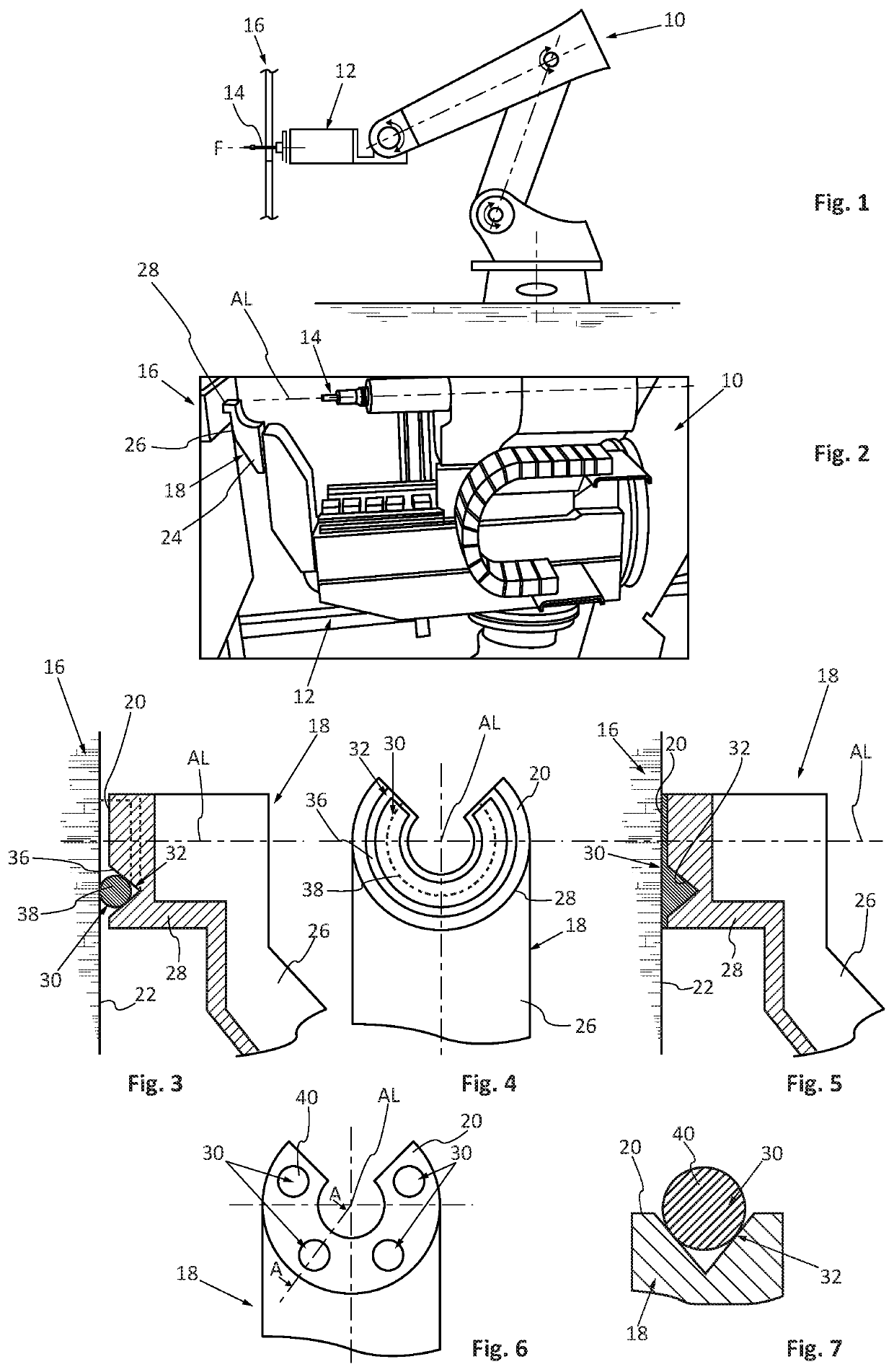
[0025]FIGS. 1 and 2 depict a robot arm 10 equipped with an effector 12. This effector 12 supports at least one tool 14 configured to perform an operation on a region of a workpiece 16.

[0026]By way of example, the tool 14 is a drill bit configured to make a drilling in the workpiece 16 which may, for example, be an aircraft fuselage panel.

[0027]The effector 12 comprises a support leg 18 which comprises at least one contact surface 20 configured to bear against a face 22 of the workpiece 16 near the zone impacted by the tool.

[0028]For the remainder of the description, the longitudinal axis AL is an axis coincident with the normal to face 22 of the workpiece 16 at the point of contact between the tool 14 and the workpiece 16. A longitudinal plane is a plane containing the longitudinal axis AL. A transverse plane is a plane perpendicular to the longitudinal axis AL.

[0029]In operation, in the case of a drilling tool, the tool 14 has a cutting movement which corresponds to a rotational mo...


PUM


Abstract

An effector includes at least one contact surface configured to bear against a face of a workpiece near a zone of the workpiece that is impacted by a tool supported by the effector. The contact surface includes at least one interface made of a ductile material interposed between the contact surface and the face of the workpiece.

Description

FIELD OF THE INVENTION[0001]The present application relates to an effector comprising a contact surface having an interface made of a ductile material.BACKGROUND OF THE INVENTION[0002]An effector is a tool holder fixed to the end of a robot arm and which supports at least one tool configured to perform an operation on a workpiece, such as, for example, a machine tool.[0003]As the robot does not have a rigid structure, according to one embodiment, the effector comprises a contact surface configured to bear against the workpiece near the tool.[0004]In order to guarantee good machining quality, it is necessary to guarantee good rigidity between the contact surface of the effector and the workpiece that is to be machined. In addition, during machining, the contact surface of the effector must not move relative to the workpiece that is to be machined. If it does, and if the machine tool slips on the surface of the workpiece that is to be machined, it generates unacceptable machining mark...

Claims


Application Information

Patent Timeline
Patent Type & Authority Patents(United States)
IPC IPC(8): B23Q3/16B25J15/00
CPCB25J15/0095B25J15/0019B23Q3/16Y10S901/41
Inventor DE MATTIA, DENISBATARD, GILLESGOHIER, SEBASTIANQUILLAUD, SÉBASTIEN
Owner AIRBUS OPERATIONS (SAS)
Learn More