
Infrared thermographic porosity quantification in composite structures

a composite structure and infrared thermography technology, applied in the direction of material flaw investigation, optical radiation measurement, instruments, etc., can solve the problems of contaminating certain test parts, consuming time-consuming ultrasonic porosity measurement, and affecting the quality of composite structure analysis results

Active Publication Date: 2020-06-23
THE BOEING CO
View PDF14 Cites 2 Cited by
  • Summary
  • Abstract
  • Description
  • Claims
  • Application Information

AI Technical Summary

Problems solved by technology

However, ultrasonic inspection techniques still come with various drawbacks.
In particular, ultrasonic porosity measurements can be time consuming, and require direct access to or contact with the test part.
Ultrasonic inspection also requires couplants which not only contaminate certain test parts, but also adds additional costs and delays.
Furthermore, ultrasonic signals are susceptible to attenuation from porous layers of structures or materials situated closer to the ultrasonic detector, and are thereby blind, or at least much less sensitive, to structures or materials situated behind or underneath detected porous structures or materials.

Method used


Image

  • Infrared thermographic porosity quantification in composite structures
  • Infrared thermographic porosity quantification in composite structures
  • Infrared thermographic porosity quantification in composite structures

Examples


Embodiment Construction

[0017]Although the following sets forth a detailed description of numerous different embodiments, it should be understood that the legal scope of protection is defined by the words of the claims set forth at the end of this patent. The detailed description is to be construed as exemplary only and does not describe every possible embodiment since describing every possible embodiment would be impractical, if not impossible. Numerous alternative embodiments could be implemented, using either current technology or technology developed after the filing date of this patent, which would still fall within the scope of the claims defining the scope of protection. It should also be understood that, unless a term is expressly defined herein, there is no intent to limit the meaning of that term, either expressly or by implication, beyond its plain or ordinary meaning, and such term should not be interpreted to be limited in scope based on any statement made in any section of this patent other t...


PUM

PropertyMeasurementUnit
porosityaaaaaaaaaa
thicknessaaaaaaaaaa
thermal testaaaaaaaaaa

Abstract

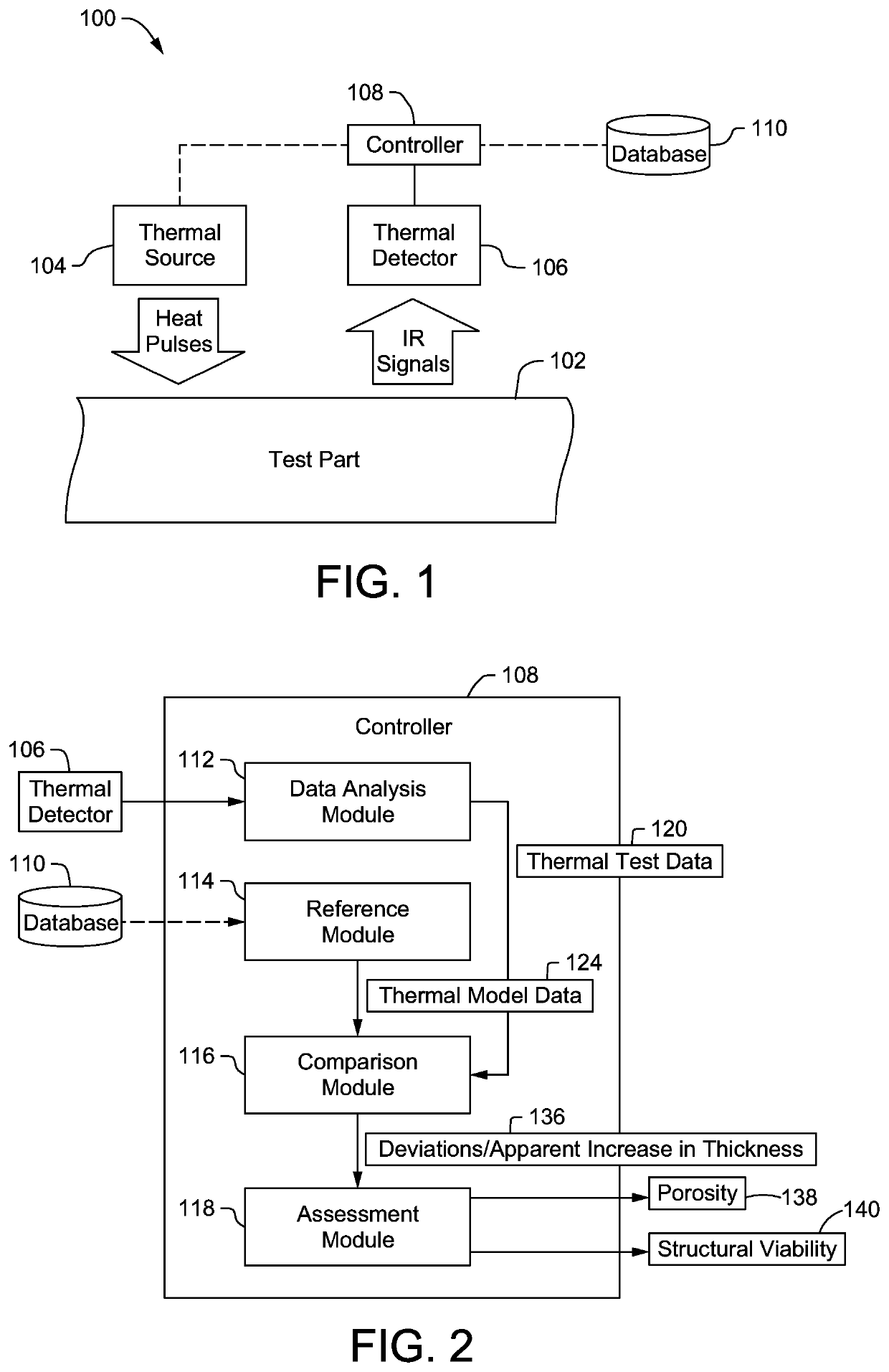
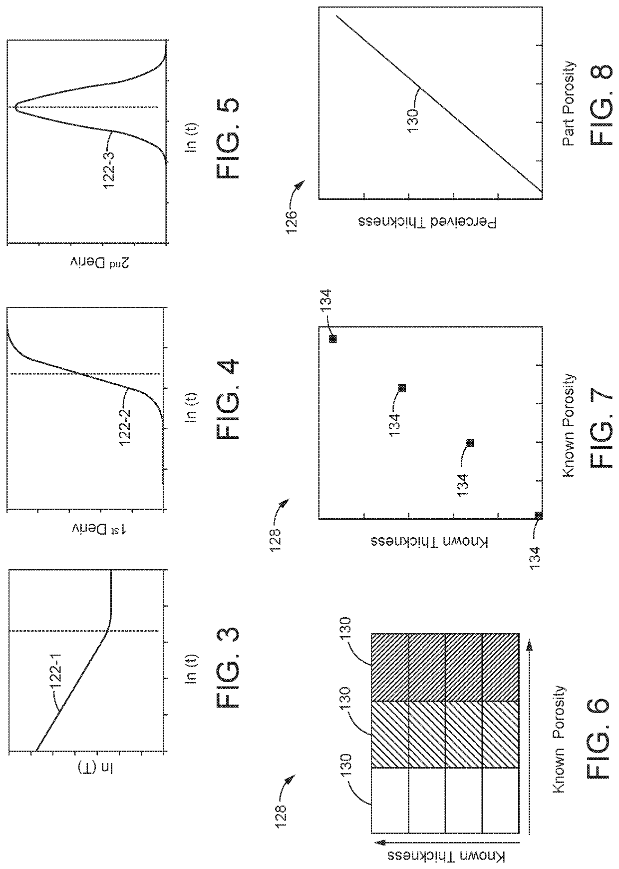
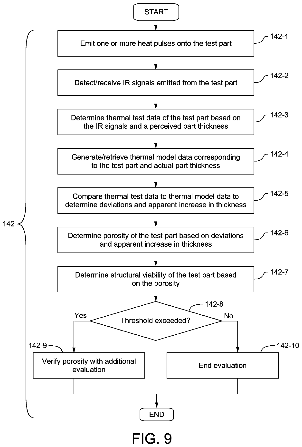
An infrared (IR) thermography system for inspecting porosity of a test part of a given thickness is provided. The IR thermography system may include a thermal detector configured to detect IR signals emitted from the test part, and a controller in electrical communication with at least the thermal detector. The controller may be configured to at least determine thermal test data associated with the test part based on the IR signals, generate thermal model data based on the thickness of the test part, and determine porosity of the test part based on a comparison between the thermal test data and the thermal model data.

Description

TECHNICAL FIELD[0001]The present disclosure relates generally to structural analyses of composite structures, and more particularly, to apparatus, systems and methods for evaluating porosity of a composite structure.BACKGROUND[0002]Evaluations of the structural integrity of a composite is of great interest to various industries including the aerospace industry. While the structural integrity of a test part may be examined using different methods or techniques, one category of techniques assess structural viability based on porosity measurements. Moreover, among the available means for measuring porosity, ultrasonic inspection is widely favored and used for its ability to detect relatively low levels of porosity. However, ultrasonic inspection techniques still come with various drawbacks. In particular, ultrasonic porosity measurements can be time consuming, and require direct access to or contact with the test part. Ultrasonic inspection also requires couplants which not only contam...

Claims


Application Information

Patent Timeline
Patent Type & Authority Patents(United States)
IPC IPC(8): G01J5/00G01N15/08G01N25/72G01J5/02
CPCG01J5/02G01N15/088G01N25/72G01N2015/0846G01N15/08
Inventor THOMPSON, JEFFREY G.GEORGESON, GARY E.HOLMES, TYLER M.
Owner THE BOEING CO
Learn More