Device for lifting one or a plurality of articles from a roller conveyor

a technology of roller conveyors and trolleys, which is applied in the direction of lifting devices, conveyors, packaging, etc., can solve the problems that small goods, transported on roller conveyors, can slip, tip over or fall, and cannot always be avoided, so as to prevent slippage, tipping over or even falling of small objects

Active Publication Date: 2020-07-28
DEMATIC
View PDF12 Cites 2 Cited by
  • Summary
  • Abstract
  • Description
  • Claims
  • Application Information

AI Technical Summary

Benefits of technology

[0005]In accordance with aspects of the invention it has become known that when the tines can be expanded in the direction transverse to the longitudinal extension thereof in order to form an expanded carrier surface it becomes possible, owing to the enlarged support surface, to prevent slipping, tipping-over or even falling of small objects or articles. That is, the carrier surface of the tines is expanded when picking up (lifting) the articles in order to form a secure standing surface (in a reversible manner).
[0008]In order to effect easy folding-in of the support during lowering, provision can be made that the vertical guide comprises a funnel-shaped inlet. Therefore, as the tine is being lowered, the support is folded-in into a vertical position into the guide by force but gently so that it can be inserted between the rollers. The support can be folded out mechanically (slotted link, lever mechanism) or actively via an actuator (actuating drive, pneumatic cylinder, etc.). In particular, the use of a spring force or magnetism is feasible.

Problems solved by technology

Particularly small goods, however, which are transported on roller conveyors can slip, tip over or fall when being lifted by means of a conventional fork mechanism or belt lifting mechanism.
In particular in the area of packet transportation, this problem cannot always be avoided by using smaller roller and fork spacings.

Method used


Image

  • Device for lifting one or a plurality of articles from a roller conveyor
  • Device for lifting one or a plurality of articles from a roller conveyor
  • Device for lifting one or a plurality of articles from a roller conveyor

Examples


Embodiment Construction

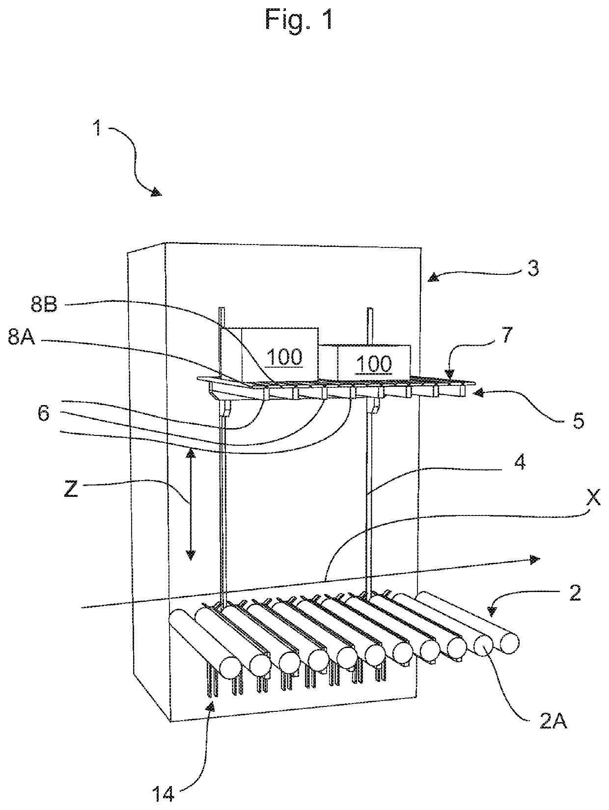
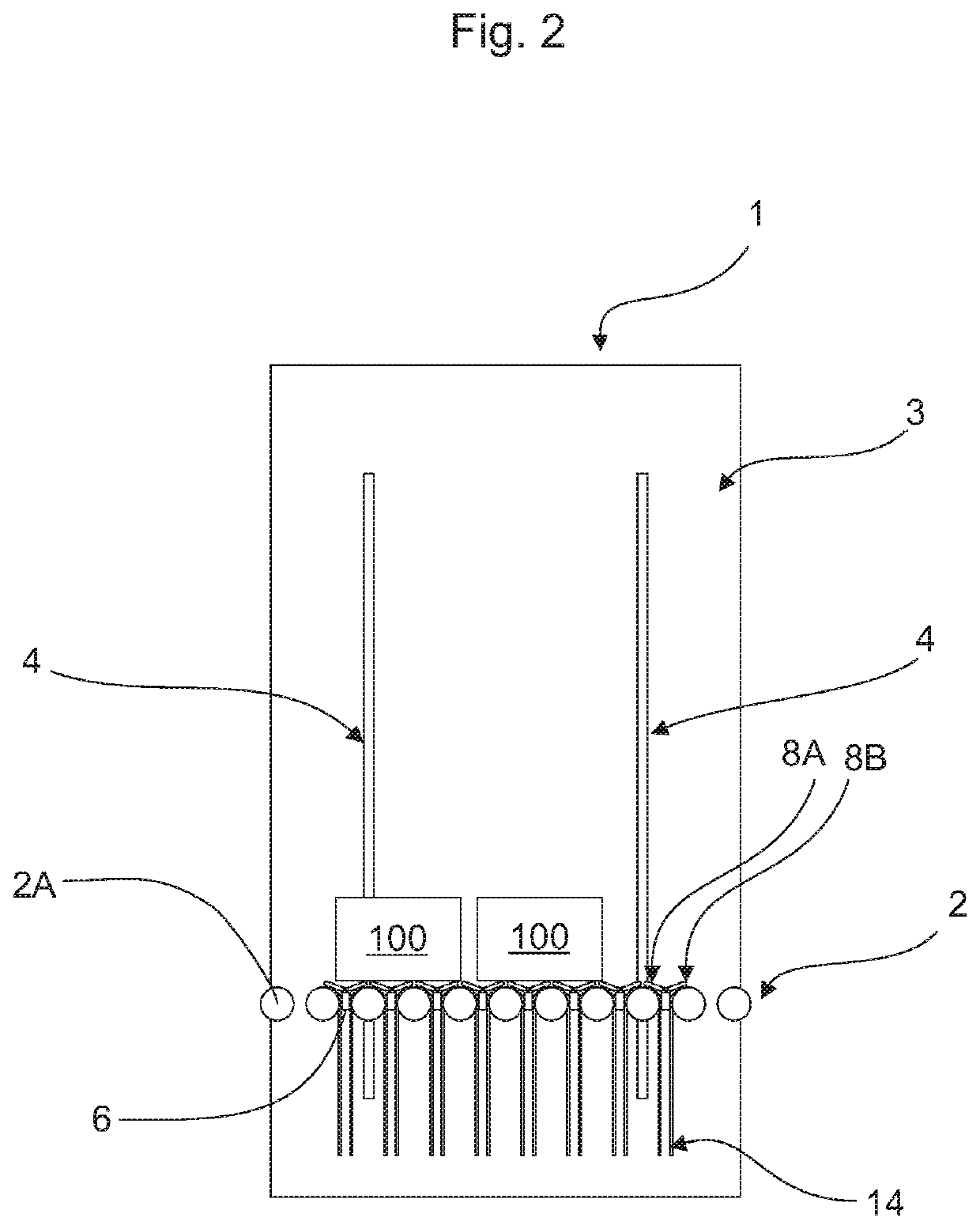
[0017]The present invention will now be described with reference to the accompanying drawings. The drawings illustrate a device designated as a whole by 1 for lifting or lowering an article 100 from a roller conveyor 2 in accordance with the present invention.

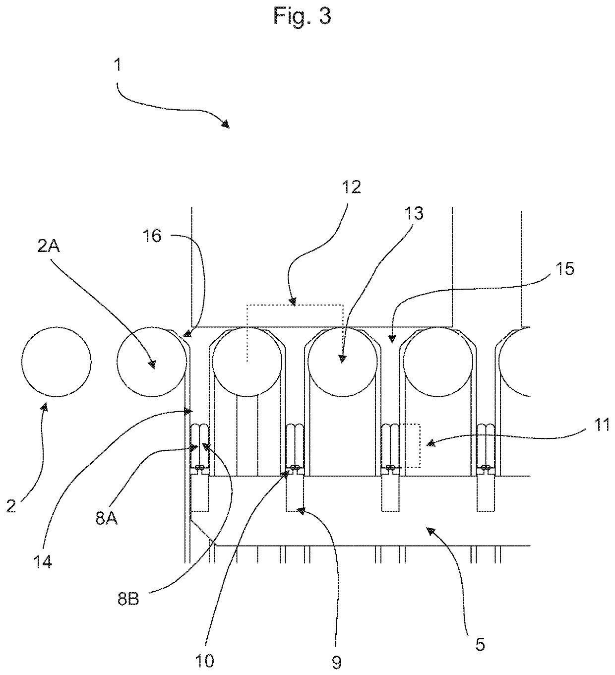
[0018]In the illustrated embodiment, the device 1 comprises a frame 3 which comprises two vertically orientated and horizontally space-apart rails 4 on which is disposed a fork 5 which can be raised and lowered in the direction of the arrow Z and has a plurality of spaced-apart elongate tines 6. The frame 3 is disposed laterally next to the roller conveyor 2 such that the tines 6 of the fork 5 extend between the rollers 2A but the base of the fork can be guided past the rollers 2A.

[0019]During lifting, the tines 6 form a carrier surface 7 for the article 100. In the lowered (bottom) position, the fork 5 is disposed with the tines 6 between the rollers 2A of the roller conveyor 2 such that articles 100 can be conveyed past in an...


PUM


Abstract

Device for lifting an article from a roller conveyor having a fork that can be raised and lowered, and having a plurality of spaced-apart elongate tines which, in the lowered position, move with the tines between or below the rollers of the roller conveyor in order to lift one or a plurality of articles from the rollers as the fork is being raised into the raised position with the tines, where the tines form a carrier surface for the article and the tines can be expanded in the direction transverse to the longitudinal extension thereof in order to form an expanded carrier surface.

Description

CROSS REFERENCE TO RELATED APPLICATION[0001]The present application claims priority of German patent application DE 10 2018 103 896.8, filed Feb. 21, 2018.BACKGROUND AND FIELD OF THE INVENTION[0002]The invention relates to a device for lifting one or a plurality of articles from a roller conveyor by a fork which can be raised and lowered having one or a plurality of spaced-apart elongate tines which, in the lowered position, are lowered with the tines between or below the rollers of the roller conveyor in order to lift the article(s) from the rollers as the fork is being raised into the raised position with the tines, wherein the tines form a carrier surface for the article.[0003]The use of forklifting devices is known for lifting objects from the rollers of roller conveyors or lowering them onto the rollers thereof by means of tines of the fork engaging between the rollers. Particularly small goods, however, which are transported on roller conveyors can slip, tip over or fall when ...

Claims


Application Information

Patent Timeline
Patent Type & Authority Patents(United States)
IPC IPC(8): B65G47/64B65G47/57B65G47/51B66F9/12B66F9/02
CPCB66F9/12B65G47/57B66F9/02B65G47/643B65G47/5181B65G2207/14B65G2201/02B65G2207/18
Inventor JARR, DANIELLEWANDOSKE, MAX REINHARDHUBERTH, DANIEL
Owner DEMATIC
Why Eureka
Try Eureka