Vessel sealing instrument

a sealing instrument and valve technology, applied in the field of valve sealing instruments, can solve the problems of not being able to safely coagulate the arteries, shred or tear, and the lumen may not be properly or effectively sealed

Active Publication Date: 2020-08-04
TYCO HEALTHCARE GRP LP
View PDF308 Cites 3 Cited by
  • Summary
  • Abstract
  • Description
  • Claims
  • Application Information

AI Technical Summary

Problems solved by technology

The article states that it is not possible to safely coagulate arteries with a diameter larger than 2 to 2.5 mm.
Below this range, the seal may shred or tear and above this range the lumens may not be properly or effectively sealed.
However, some of these designs may not provide uniformly reproducible pressure to the blood vessel and may result in an ineffective or non-uniform seal.
Many of these instruments include blade members or shearing members which simply cut tissue in a mechanical and / or electromechanical manner and are relatively ineffective for vessel sealing purposes.
Other instruments rely on clamping pressure alone to procure proper sealing thickness and are not designed to take into account gap tolerances and / or parallelism and flatness requirements which are parameters which, if properly controlled, can assure a consistent and effective tissue seal.
For example, it is known that it is difficult to adequately control thickness of the resulting sealed tissue by controlling clamping pressure alone for either of two reasons: 1) if too much force is applied, there is a possibility that the two poles will touch and energy will not be transferred through the tissue resulting in an ineffective seal; or 2) if too low a force is applied, a thicker less reliable seal is created.

Method used


Image

  • Vessel sealing instrument
  • Vessel sealing instrument
  • Vessel sealing instrument

Examples


Embodiment Construction

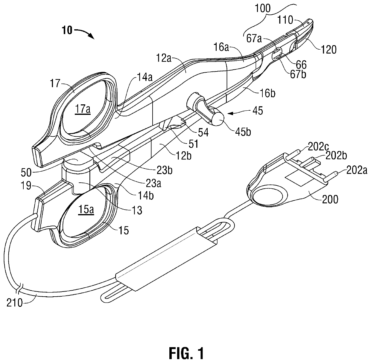
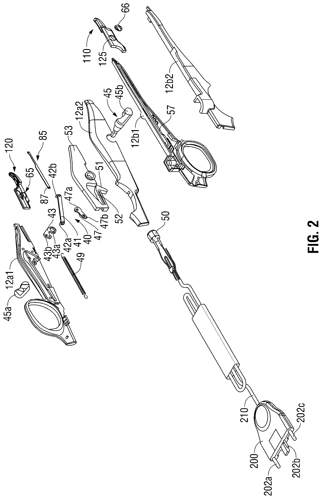
[0026]Referring initially to FIGS. 1 and 2, a forceps 10 for use with open surgical procedures includes elongated shaft portions 12a and 12b each having a proximal end 14a, 14b and a distal end 16a and 16b, respectively. In the drawings and in the description that follows, the term “proximal”, as is traditional, will refer to the end of the forceps 10 that is closer to the user, while the term “distal” will refer to the end that is further from the user.

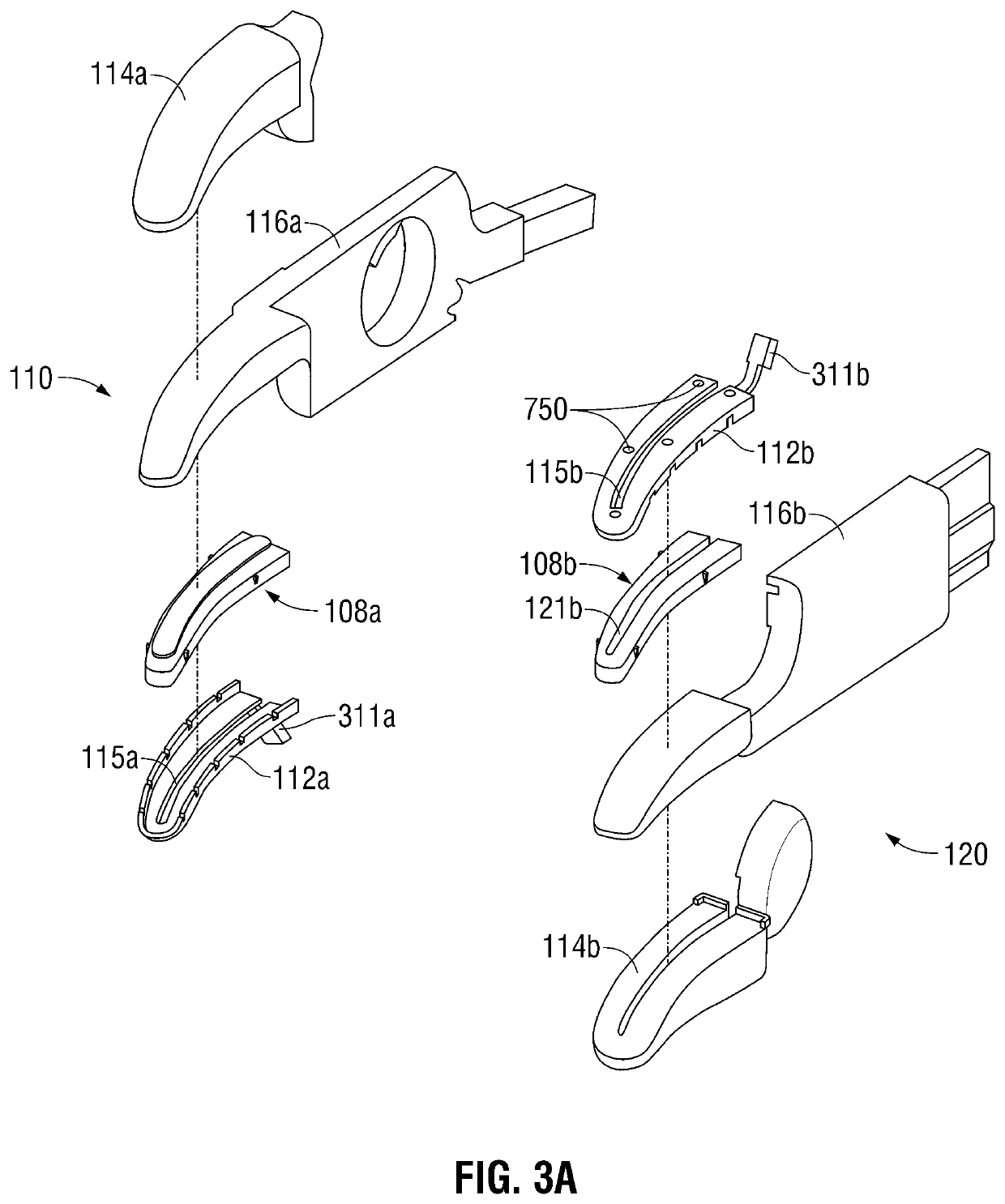
[0027]The forceps 10 includes an end effector assembly 100 that attaches to the distal ends 16a and 16b of shafts 12a and 12b, respectively. The end effector assembly 100 includes pair of opposing jaw members 110 and 120 that are pivotably connected and movable relative to one another about a pivot 65 (FIG. 2) to grasp tissue. Pivot 65 is disposed on a proximal end of jaw member 120 and includes opposing halves 65a and 65b disposed on opposing sides of a channel 126 (FIG. 4C) that is configured to facilitate reciprocation of a cuttin...


PUM


Abstract

A bipolar electrosurgical instrument includes first and second shafts each having a jaw member extending from its distal end. Each jaw member is adapted to connect to a source of electrosurgical energy such that the jaw members are capable of selectively conducting energy through tissue held therebetween. A knife channel is configured to reciprocate a cutting mechanism therealong. An actuator selectively advances the cutting mechanism. A switch is disposed on the first shaft and is configured to be depressed between a first position and at least one subsequent position upon biasing engagement with a mechanical interface disposed on the second shaft. The first position of the switch relays information to the user corresponding to a desired pressure on tissue and the at least one subsequent position is configured to activate the source of electrosurgical energy to supply electrosurgical energy to the jaw members.

Description

CROSS-REFERENCE TO RELATED APPLICATIONS[0001]The present application is a continuation of U.S. patent application Ser. No. 15 / 791,552 filed Oct. 24, 2017, now U.S. Pat. No. 10,201,384, which is a continuation of U.S. patent application Ser. No. 15 / 018,985 filed Feb. 9, 2016, now U.S. Pat. No. 9,795,439, which is a continuation of U.S. patent application Ser. No. 14 / 795,246 filed Jul. 9, 2015, now U.S. Pat. No. 9,498,279, which is a continuation of U.S. patent application Ser. No. 12 / 897,346 filed Oct. 4, 2010, now U.S. Pat. No. 9,655,672, the entire contents of each of which are incorporated herein by reference.INTRODUCTION[0002]The present disclosure relates to forceps used for open surgical procedures. More particularly, the present disclosure relates to a forceps that applies electrosurgical current to seal tissue.BACKGROUND[0003]A hemostat or forceps is a simple plier-like tool which uses mechanical action between its jaws to constrict vessels and is commonly used in open surgic...

Claims


Application Information

Patent Timeline
Patent Type & Authority Patents(United States)
IPC IPC(8): A61B18/14A61B90/00A61B34/00A61B18/00
CPCA61B90/03A61B34/76A61B18/1442A61B2090/034A61B2018/1455A61B2018/1412A61B2018/00607A61B2018/0063A61B2018/00404A61B2018/00601A61B2090/065A61B2018/00309A61B90/06A61B2018/00916A61B18/12A61B17/28A61N1/18
Inventor ARTALE, RYAN C.ROY, JEFFREY M.MOUA, TONYBUTCHER, DENNIS W.DICKHANS, WILLIAM J.JOSEPH, DANIEL A.WAALER, LUKEPERRY, CYNTHIA M.COLLINS LONG, MEGHAN
Owner TYCO HEALTHCARE GRP LP
Why Eureka
Try Eureka