Indicator for Knife Location in a Stapling or Vessel Sealing Instrument

a technology for sealing instruments and indicators, which is applied in the field of indicators for knife location in sealing or stapling instruments, can solve the problems of inability to see the moving knife in the jaw of the tool, inadvertent tissue damage, etc., and achieve the effect of improving the surgeon's intuitive sense of the procedur

Active Publication Date: 2012-08-16
INTUITIVE SURGICAL OPERATIONS INC
View PDF13 Cites 72 Cited by
  • Summary
  • Abstract
  • Description
  • Claims
  • Application Information

AI Technical Summary

Benefits of technology

[0007]Improved systems and methods for indicating a position of a tool of an end effector are provided. The claimed methods and systems relate to displaying an image of a motor-driven tool clamping a material on a user interface, the tool having a first and second jaw for clamping the material and a cutting element (e.g. a knife or blade) for cutting the material, and superimposing on the user interface display a visual indicator of a position of the cutting element. The cutting element (e.g. blade, knife) comprises various positions, wherein a position represents a position and/or an orientation of the cutting element. In many embodiments, the tool comprises an end effector having a first and second jaw and a knife disposed within the end effector such that the knife moves along a longitudinal axis of the jaws from a pre-cut position to a cut-complete position, thereby cutting the tissue clamped between the jaws. The knife positions may include any or all of: a pre-cut position, a cut-complete position, a cut-incomplete position, and a exposed position. The described metho

Problems solved by technology

This is particularly useful on the rare occasion when the movement of the knife should stall leaving the knife in an “exposed” or “cut-incomplete” position, which may potentially cause inadvertent tissue damage if th

Method used


Image

  • Indicator for Knife Location in a Stapling or Vessel Sealing Instrument
  • Indicator for Knife Location in a Stapling or Vessel Sealing Instrument
  • Indicator for Knife Location in a Stapling or Vessel Sealing Instrument

Examples


Embodiment Construction

[0028]In the following description, various embodiments of the present invention will be described. For purposes of explanation, specific configurations and details are set forth in order to provide a more thorough understanding of the embodiments. However, it will also be apparent to one skilled in the art that the present invention may be practiced without the specific details. Furthermore, well-known features may be omitted or simplified in order not to obscure the embodiment being described.

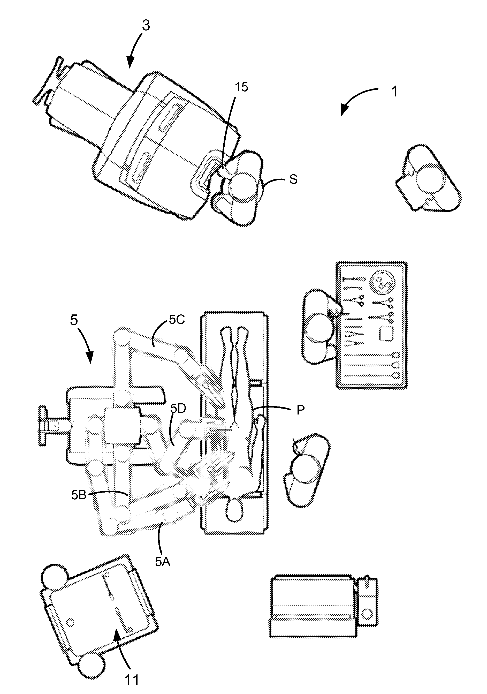
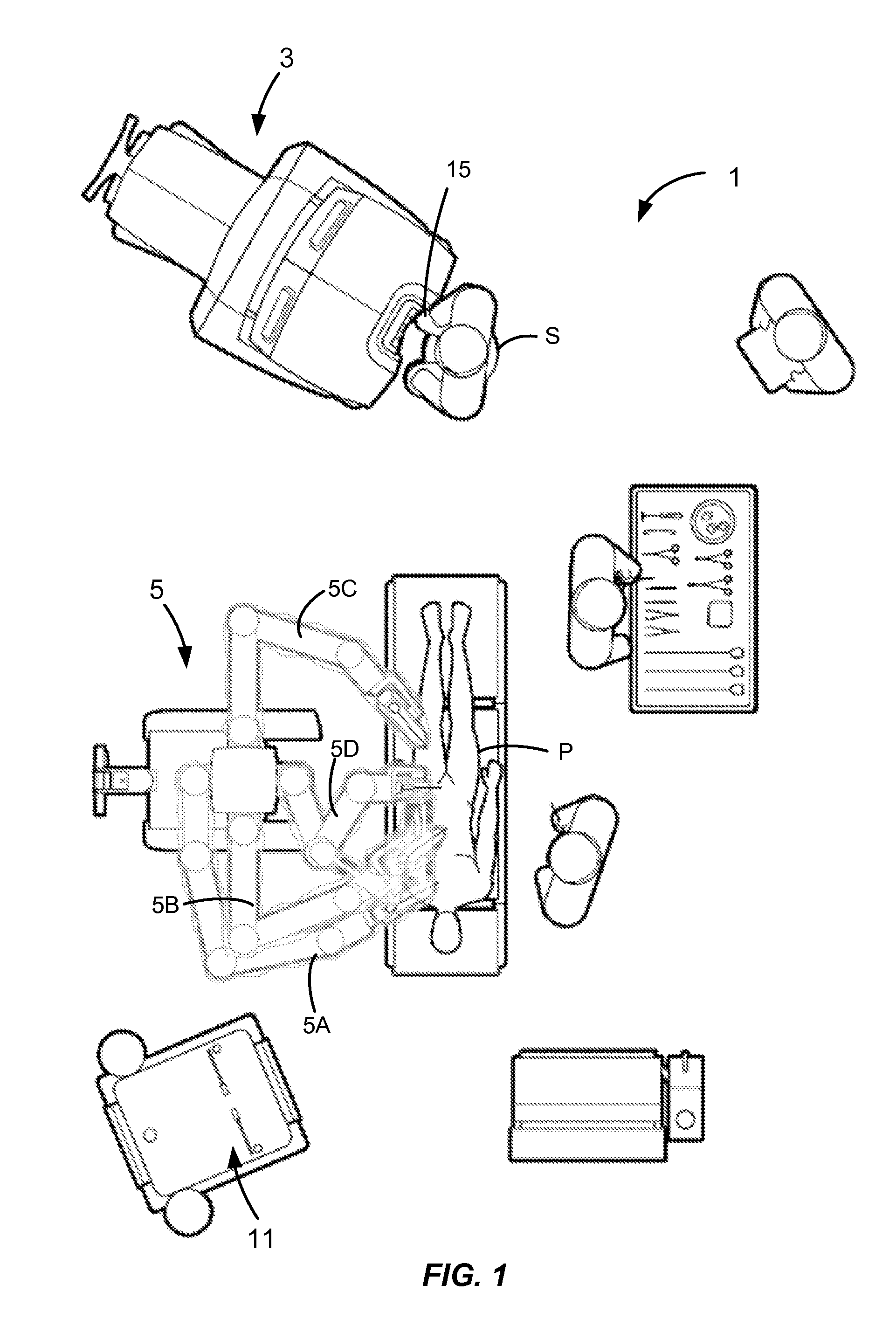
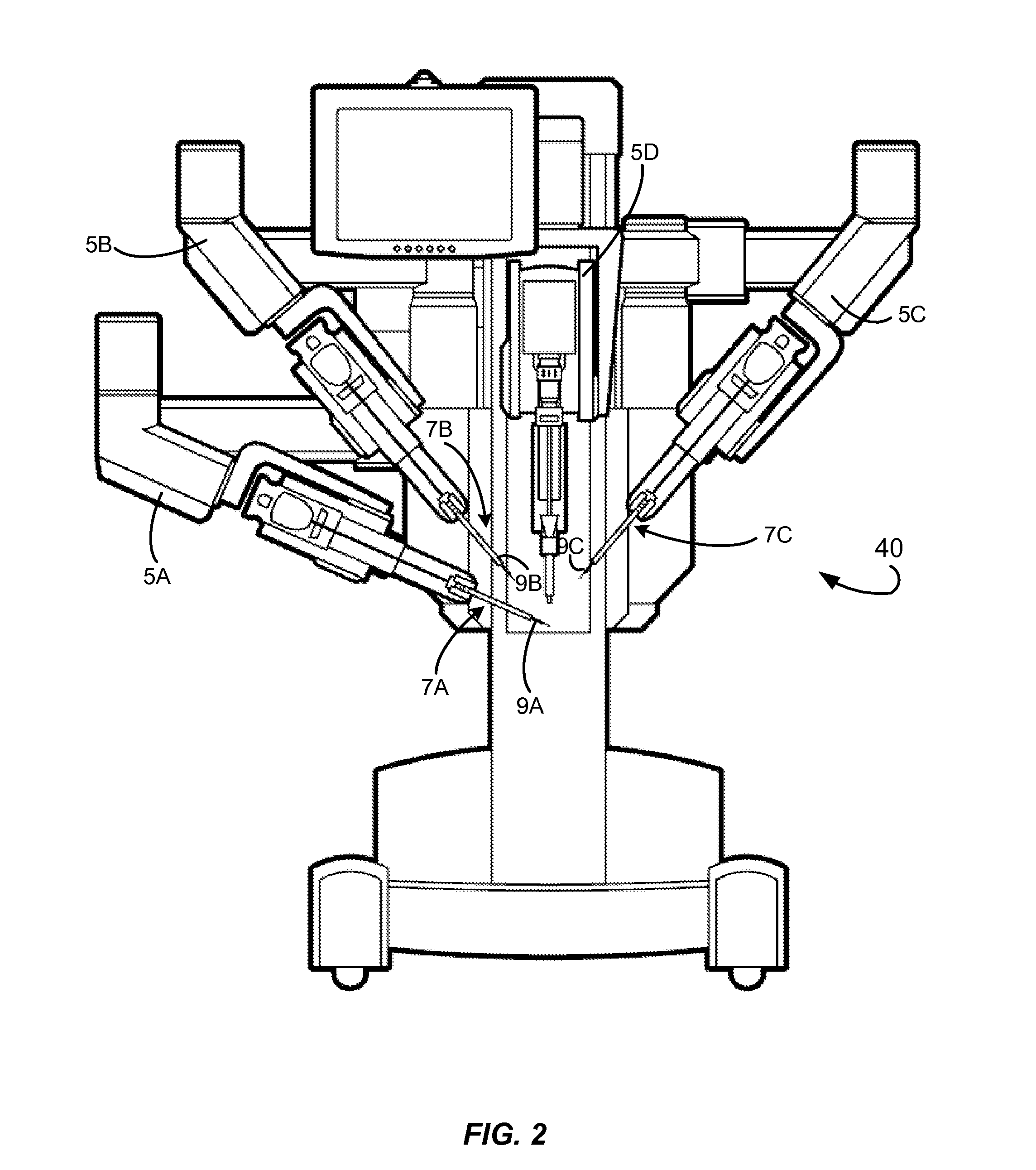
[0029]Improved systems and methods for indicating a location and / or an orientation of a cutting element on a tool during a cutting procedure are provided. The claimed methods and systems may be used in conjunction with other methods of tracking so as to allow a user to perceive a position or orientation of the cutting element relative to the tool. These methods and systems are usefully in robotic systems where a user may not be able to see the cutting element during cutting, which is particul...


PUM


Abstract

Systems and methods are provided for displaying an image of a tracked tool on a user interface, wherein at least a portion of the tool is hidden from view in any image on a user interface at any point during a procedure. The tool may include a cutting tool having jaws for clamping a material and a knife for cutting the clamped material, and superimposing an indicator of a knife position on the display during and/or after cutting. The knife position may include a location and/or orientation of the knife, including any or all of a pre-cut, cut-complete, cut-incomplete and an exposed position. The disclosed systems and methods allows a user to view the knife position in applications where the knife may not be visible to a user, which is particularly useful for clamping and cutting a body tissue with a robotic surgical system in minimally invasive procedures.

Description

CROSS-REFERENCES TO RELATED APPLICATIONS[0001]The present application is a non-provisional of, and claims the benefit of U.S. Provisional Patent Application No. 61 / 443,115, filed Feb. 15, 2011, the entire contents of which are incorporated herein by reference.[0002]This application is related to the following applications: U.S. application Ser. No. 12 / 705,418, entitled “Cut and Seal Instrument” (Attorney Docket No. ISRG 02180 / US), filed on Feb. 12, 2010; U.S. application Ser. No. 12 / 415,332 (Attorney Docket No. ISRG 01510 / US), filed on Mar. 31, 2009; and U.S. application Ser. No. 11 / 478,531 (Attorney Docket No. ISRG 0010 / US), filed on Jun. 29, 2006, the entireties of which are hereby incorporated by reference.BACKGROUND OF THE INVENTION[0003]Minimally invasive surgeries performed by robotic surgical systems are known and commonly used in clinical procedures where it is advantageous for a human not to perform surgery directly. One example of such a system is the minimally invasive ro...

Claims


Application Information

Patent Timeline
IPC IPC(8): A61B19/00
CPCA61B17/07207A61B19/5244A61B2019/5251A61B19/2203A61B2019/5259A61B34/30A61B2034/2051A61B2034/2059A61B2017/00398A61B2017/00022A61B2017/07285A61B90/98A61B2090/0803A61B18/1445A61B2018/1455A61B34/20A61B18/1482A61B17/072A61B90/37A61B2018/00607A61B2017/00119A61B18/14
Inventor ROBINSON, DAVID
Owner INTUITIVE SURGICAL OPERATIONS INC
Why Eureka
Try Eureka