Swim fin with an upper portion having debossed regions and triple-bladed rails

a technology of debossed regions and fins, applied in the direction of swim fins, etc., can solve the problems of increased pressure on the foot pocket, particularly uncomfortable specific pressure points or “hot spots” that users may experience, and achieve the effect of reducing cross-sectional thickness

Active Publication Date: 2020-08-18
TYR SPORT INC
View PDF69 Cites 3 Cited by
  • Summary
  • Abstract
  • Description
  • Claims
  • Application Information

AI Technical Summary

Benefits of technology

The patent describes a shoe design with debossed regions and ridges that improve its stiffness and comfort. The design also includes a top channel and bottom channel between the blades, as well as a thicker middle blade that has a smaller lateral length. The technical effects of this design include improved stability, comfort, and aesthetics.

Problems solved by technology

The technical problem addressed in this patent text is the discomfort experienced by swim fins users due to the increased pressure from the foot pocket caused by the increased water resistance of training swim fins. The patent aims to improve the ease of use, comfort, and functionality of swim fins to address this problem.

Method used


Image

  • Swim fin with an upper portion having debossed regions and triple-bladed rails
  • Swim fin with an upper portion having debossed regions and triple-bladed rails
  • Swim fin with an upper portion having debossed regions and triple-bladed rails

Examples


Embodiment Construction

[0018]The detailed description set forth below in connection with the appended drawings is intended as a description of certain embodiments of the present disclosure, and is not intended to represent the only forms that may be developed or utilized. The description sets forth the various functions in connection with the illustrated embodiments, but it is to be understood, however, that the same or equivalent functions may be accomplished by different embodiments that are also intended to be encompassed within the scope of the present disclosure. It is further understood that the use of relational terms such as top and bottom, first and second, and the like are used solely to distinguish one entity from another without necessarily requiring or implying any actual such relationship or order between such entities.

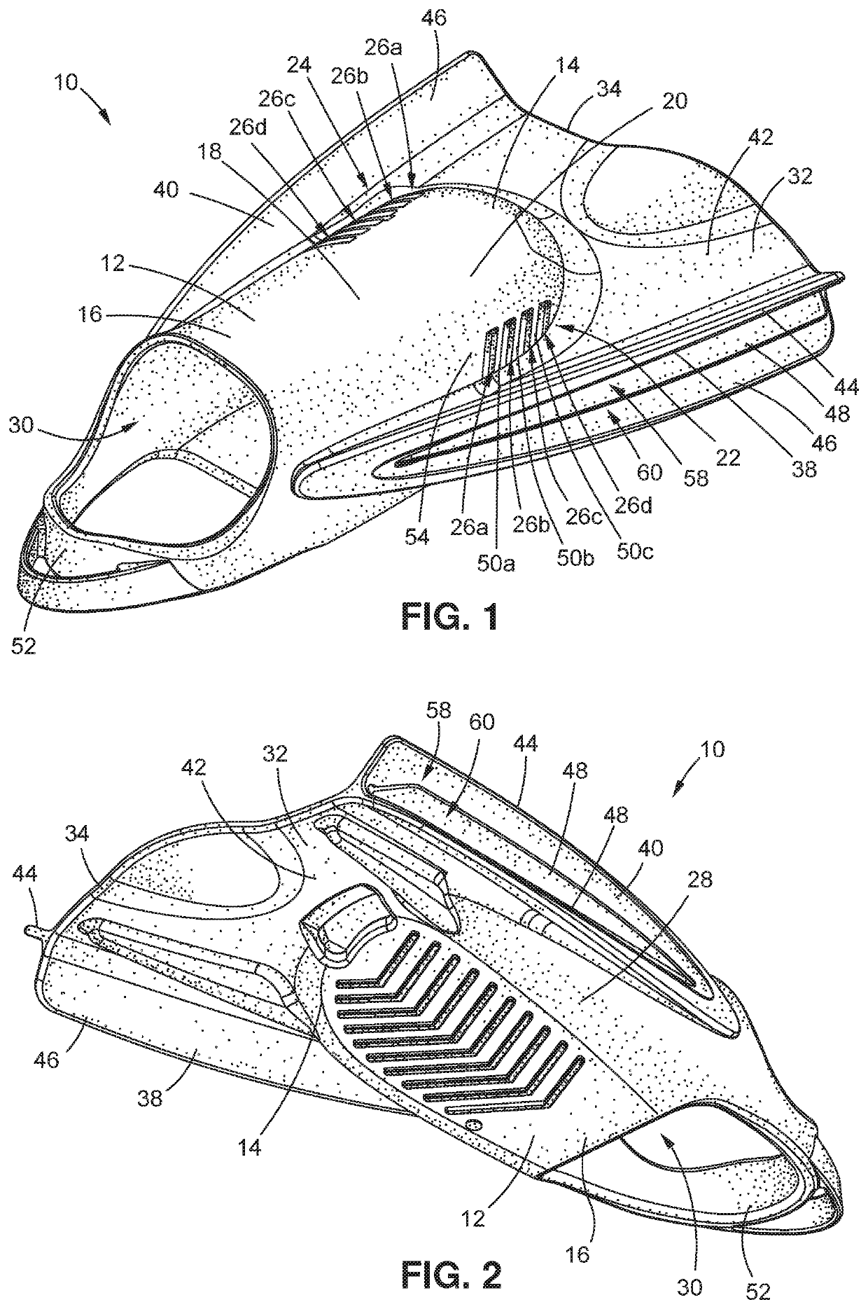
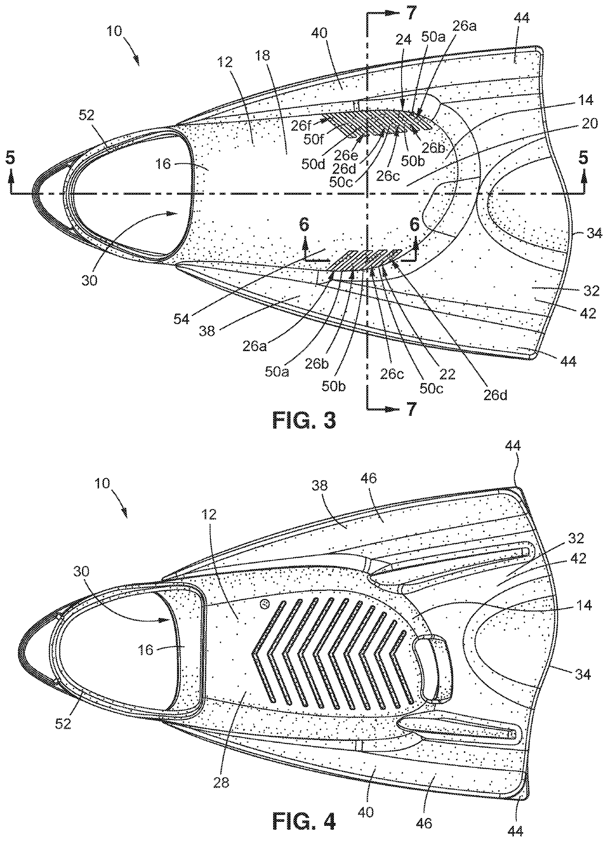
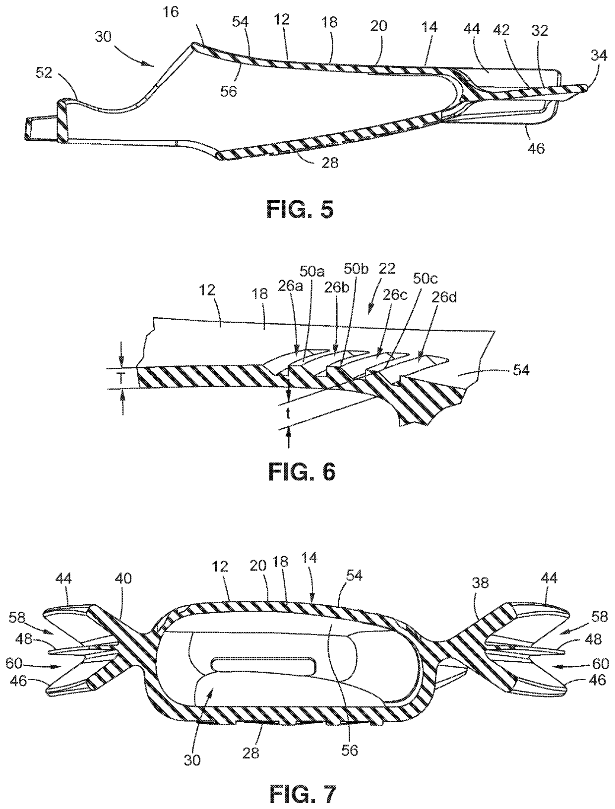
[0019]Referring now to FIG. 1, there is depicted a perspective view of a swim fin 10 according to various aspects of the inventions described herein. FIGS. 1 and 2 respectivel...


PUM


Abstract

A swim fin includes a foot pocket with a front and rear sections and an upper portion. The upper portion has a dorsal region, and first and second debossed regions with the dorsal region disposed between the debossed regions. The first and second debossed regions are laterally positionable adjacent the metatarsophalangeal joints of the foot of the user. The debossed region includes grooves formed therein. The foot pocket includes a foot pocket cavity. The swim fin further includes a fin blade extending from the front section of the foot pocket. The fin blade has a distal edge, a blade body disposed between the distal edge and the front section, and first and second triple-bladed rails. The triple-bladed rails are disposed longitudinally along the foot pocket and the blade body with the foot pocket and the blade body disposed between the first and second triple-bladed rails.

Description


Claims


Application Information

Patent Timeline
Owner TYR SPORT INC
Why Eureka
Try Eureka