Method for riveting or piercing and a device for carrying out the method

a self-piercing and riveting technology, applied in the field of riveting or self-piercing, can solve the problems of constant movement of the device, need of cable ducts, and subject to wear phenomena, and achieve the effect of simple method, long riveting length and simple calibration

Inactive Publication Date: 2005-02-22
NEWFREY
View PDF1 Cites 11 Cited by
  • Summary
  • Abstract
  • Description
  • Claims
  • Application Information

AI Technical Summary

Benefits of technology

According to an advantageous further development of the method the setting of the die and the pick-up device on the die plate or on a workpiece is detected by a measurement of the force on the drive of the die. By measuring a reference position at a defined force when the die and/or the pick-up device are set, calibration can be performed in a simple manner. The measurement of the force takes place via the housing, so the forces exerted by the die and the holding-down clamp are measured together. With this information the actual depth of the riveting or piercing, and also the length of the riveting can then be accurately determined. These reference measurements can also be used to determine the thickness of workpieces accurately and quickly. The relative displacement between die and pick-up device at the deepest point corresponds exactly to the pressing depth or the rivet head projection.
The method according to the invention in a preferred embodiment has the effect that a predetermined movement path of the die towards the workpiece, based on a desired piercing depth or a desired rivet head projection, is lengthened by the relative movement between counterforce structure and pick-up device measured by the first sensor during the riveting or piercing process. With different hardness of the material to be processed, but also even with different temperatures, etc., the forces occurring during riveting or self-piercing are different, leading to deformations of the counterforce structure which cannot be accurately determined empirically. By means of the compensation according to the invention with the relative movement measured by the first sensor, which exac...

Problems solved by technology

A disadvantage of this, however, is that the cable ducts needed for detecting the relative movement between die and pick-up device suf...

Method used


Image

  • Method for riveting or piercing and a device for carrying out the method
  • Method for riveting or piercing and a device for carrying out the method

Examples


Embodiment Construction

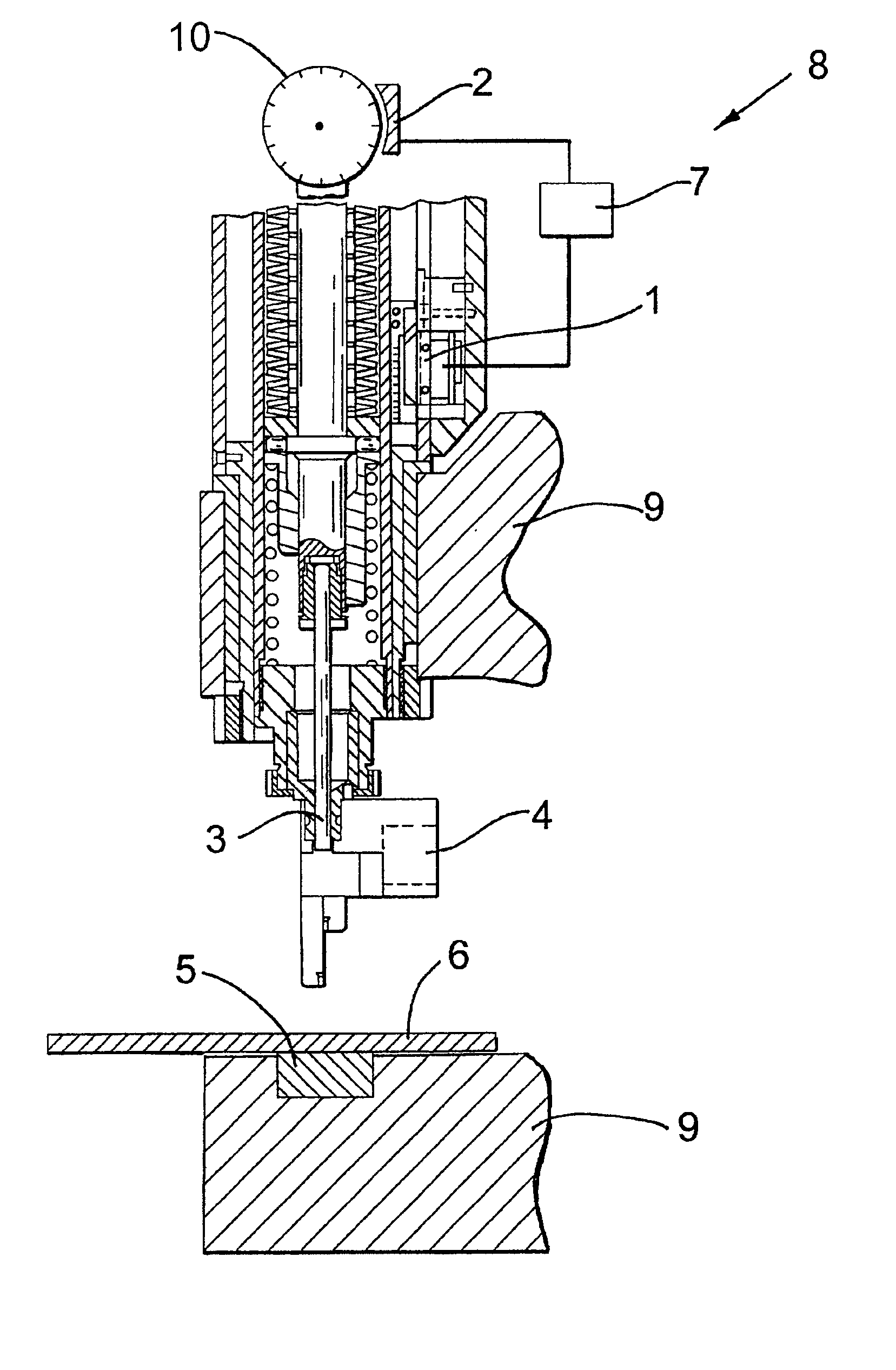
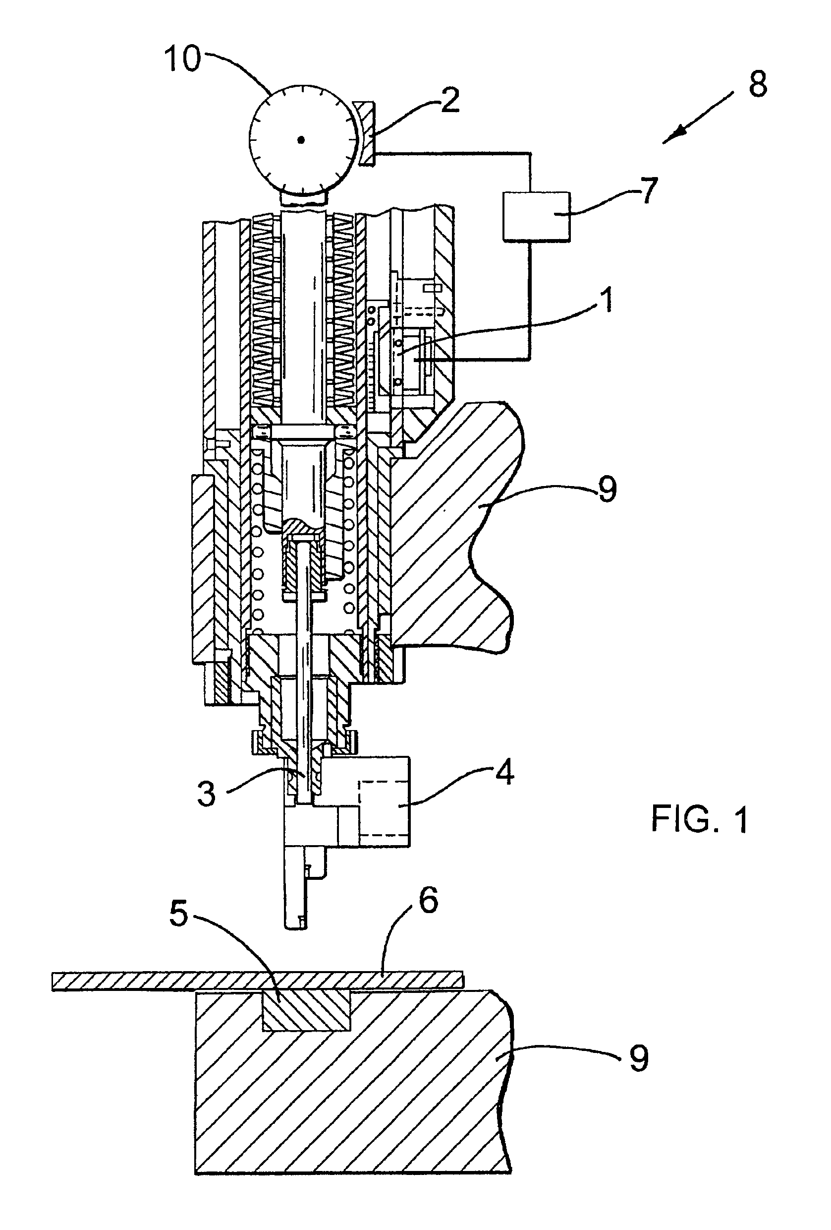
FIG. 1 shows a riveting device 8, but a self-piercing machine (not shown) could have been illustrated to show the present invention. The riveting device 8 has a counterforce structure 9 surrounding a workpiece 6 in the form of a C-shaped bracket of which only the outer portions are shown. The workpiece 6 is supported on a die plate 5. A pick-up device 4 picks up rivets, which are driven into the workpiece 6 with the aid of a die 3 driven by a drive unit 10. A first sensor 1 measures the relative movement between pick-up device 4 and counterforce structure 9. This sensor is preferably a linear path recorder consisting of a kind of ruler which makes the same movement as the pick-up device 4 and a counter which is fixed to the counterforce structure 9 and counts markings on the ruler going past it. A second sensor 2 measures the relative movement between counterforce structure 9 and die 3. Sensors of this kind are known per se and usually integrated into the drive unit 10 of the die 3....


PUM


Abstract

The method according to the invention for riveting, or self-piercing, by means of a riveting or self-piercing device (8), having a male die (3) guided by a pick-up device (4), both of which in each case can be moved towards a female die (5) and/or a workpiece (6), wherein the female die (5) and riveting or self-piercing device (8) will be connected to one another via a counterforce structure (9). The relative movement between the pick-up device (4) and the counterforce structure (9) is measured by a first sensor (1), and the relative movement between counterforce structure (9) and male die (3) is measured by a second sensor (2). The depth of the riveting or piercing is adjusted with the aid of the two measured values. The associated device allows fast, accurate detection of the thickness of a workpiece (6) and precise piercing or riveting with constant predetermined depth irrespective of variations in the quality of the material or other parameters, which can result in deformations of the counterforce structure (9) during the piercing process.

Description

BACKGROUND OF THE INVENTIONThe present invention relates to a method for riveting, or self-piercing, and a device for carrying out the method. The large forces on a workpiece which occur when a rivet is set or during piercing must be compensated by a counterforce. This is usually achieved by supporting the workpiece on a counterforce structure, which preferably substantially has the shape of a C and is therefore also usually designated as a C-bracket.For the precise setting of a rivet or accurate self-piercing it is important to know how deeply a rivet or a die has penetrated into the workpiece. This problem arises in particular when large workpieces are being processed, where the counterforce structure (C-bracket) is very large. In practice arm lengths of C-brackets occur of up to 1.5 metres. Deformation of the counterforce structure occurs in particular with large forces acting on the workpiece, so the actual self-piercing depth or the rivet head projection is determined only inac...

Claims


Application Information

Patent Timeline
IPC IPC(8): B21J15/00B21J15/28B21J15/02B21J15/10
CPCB21J15/025B21J15/28B21J15/285Y10T29/49936Y10T29/49908Y10T29/53065Y10T29/49771Y10T29/49776
Inventor BLOCHER, MICHAELMOSER, JOACHIMOPPER, REINHOLD
Owner NEWFREY
Why Eureka
Try Eureka