Vehicular headlamp

a headlamp and headlamp technology, applied in vehicle components, anti-theft devices, lighting and heating apparatus, etc., can solve the problems of not being able to achieve the light appearance other than the lighting appearance at the time of forming a light distribution pattern,

Active Publication Date: 2020-09-08
STANLEY ELECTRIC CO LTD
View PDF11 Cites 0 Cited by
  • Summary
  • Abstract
  • Description
  • Claims
  • Application Information

AI Technical Summary

Benefits of technology

[0007]The present invention has been made in light of the above circumstances, and it is an object of the present invention to provide a vehicular headlamp that can achieve lighting appearance other than lighting appearance at the time of forming a light distribution pattern for a headlamp.
[0009]According to this aspect, there can be provided a vehicular headlamp that can achieve lighting appearance other than lighting appearance at the time of forming a light distribution pattern for a headlamp.

Problems solved by technology

However, in Patent Document 1, there is a problem in that lighting appearance other than lighting appearance at the time of forming a light distribution pattern for a headlamp (e.g. the low beam light distribution pattern or the high beam light distribution pattern) cannot be achieved.

Method used


Image

  • Vehicular headlamp
  • Vehicular headlamp
  • Vehicular headlamp

Examples


Embodiment Construction

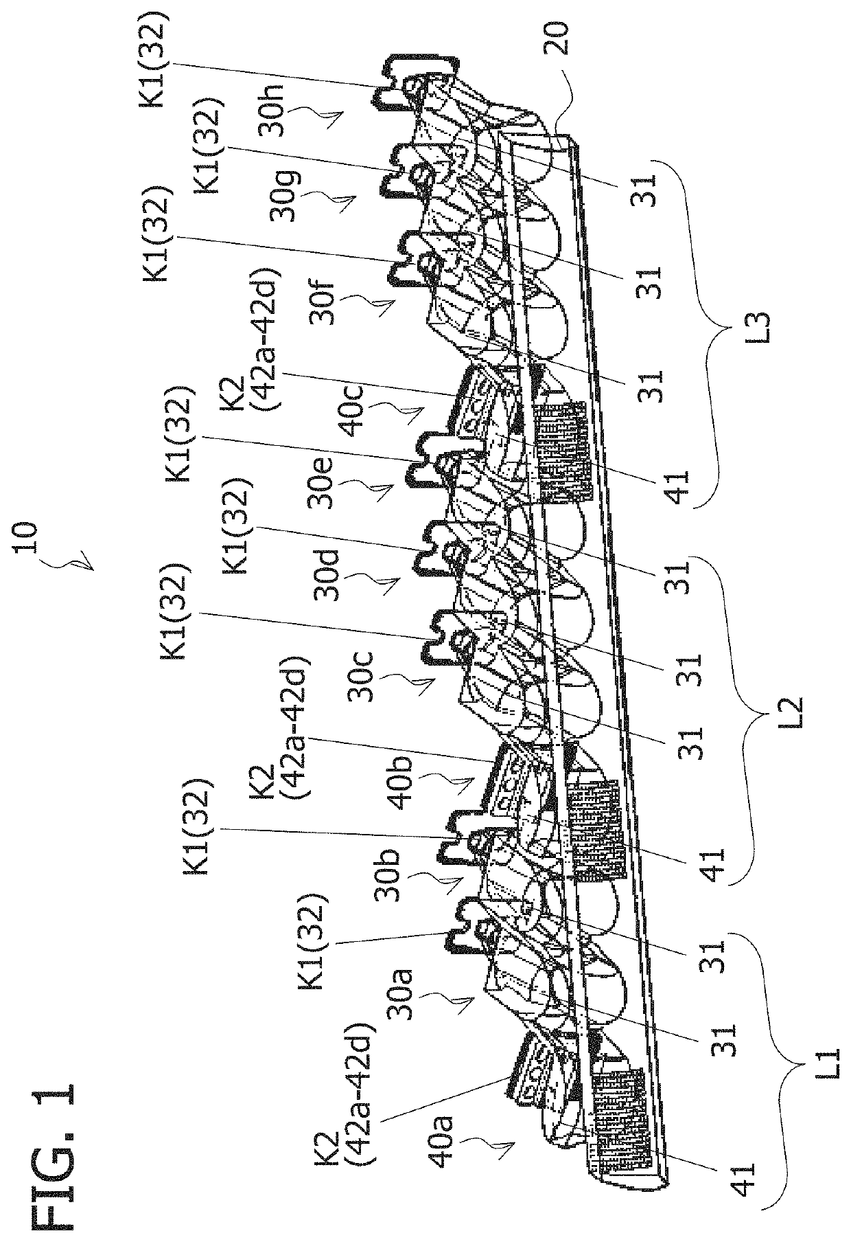
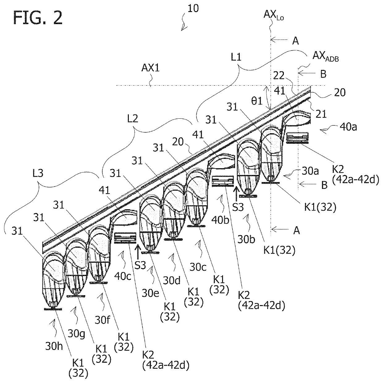
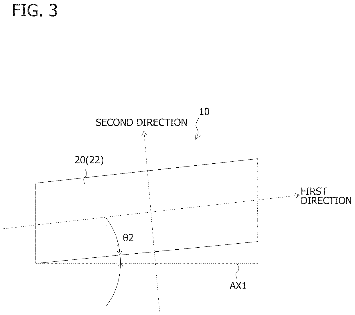
[0040]A vehicular lamp 10 (corresponding to a vehicular headlamp according to the present invention) according to an embodiment of the present invention is described below with reference to the attached drawings. Corresponding components in each drawing are denoted by the same reference symbols and overlapping descriptions are omitted.

[0041]FIG. 1 is a perspective view of the vehicular lamp 10. FIG. 2 is a top view of the vehicular lamp 10. FIG. 3 is a front view of the vehicular lamp 10.

[0042]The vehicular lamp 10 shown in FIGS. 1 to 3 is a vehicular headlamp (headlamp) and is mounted to, for example, the left and right sides on the front end of a vehicle such as an automobile. Because the vehicular lamp 10 to be mounted to both the left and right sides has a symmetrical configuration, a vehicular lamp 10 mounted to the left side at the front of a vehicle (left side facing the front of the vehicle) is described as a representative example of the vehicular lamp 10. Although not illu...


PUM


Abstract

A vehicular headlamp comprising: a front lens body extending in a predetermined direction; a plurality of optical systems disposed along the predetermined direction behind the front lens body; and a control means, wherein the plurality of optical systems each includes: a rear lens unit disposed behind the front lens body; and a light source which is disposed behind the rear lens unit and emits light which is irradiated forward permeating the rear lens unit and the front lens body in that order to form a light distribution pattern for a headlamp, and the control means individually controls lighting states of the light sources in each of the plurality of optical systems.

Description

CROSS-REFERENCE TO RELATED APPLICATION[0001]This application is based upon and claims the benefit of priority of the prior Japanese Patent Application No. 2017-254053, filed on Dec. 28, 2017, the entire contents of which are incorporated herein by reference.FIELD[0002]The present invention relates to a vehicular headlamp. More particularly, the present invention relates to a vehicular headlamp that can achieve lighting appearance other than lighting appearance at the time of forming a light distribution pattern for a headlamp is provided.BACKGROUND[0003]There is known a vehicular headlamp which includes a plurality of low beam optical systems each including a low beam lens and a low beam light source, and a plurality of high beam optical systems each including a high beam lens and a high beam light source (see, for example, Patent Document 1 (FIG. 1, etc.)).[0004]In Patent Document 1, a low beam light distribution pattern can be formed by turning off the high beam light sources and ...

Claims


Application Information

Patent Timeline
Patent Type & Authority Patents(United States)
IPC IPC(8): F21S41/663F21S43/20F21S41/27B60Q1/14F21S41/26B60Q1/50F21S41/25F21S41/275F21S41/143B60Q1/04B60R25/10F21S41/141F21S41/16
CPCF21S41/663F21S41/275F21S41/25F21S41/26F21S43/26B60Q1/143F21S41/27B60Q1/50F21S41/143F21S41/16B60R25/1003B60Q1/04F21S41/141B60Q2400/40B60Q2900/30B60Q2300/21B60Q2900/40
Inventor NISHIMURA, SHOTAKAMIOKA, KAZUMA
Owner STANLEY ELECTRIC CO LTD
Why Eureka
Try Eureka