Terminal block structure

Active Publication Date: 2020-09-08
DINKLE ENTERPRISE +1
View PDF5 Cites 0 Cited by
  • Summary
  • Abstract
  • Description
  • Claims
  • Application Information

AI Technical Summary

Benefits of technology

[0004]An object of the invention is to provide an improved terminal block structure, which ca

Problems solved by technology

Thus, material and assembli

Method used


Image

  • Terminal block structure
  • Terminal block structure
  • Terminal block structure

Examples


Example

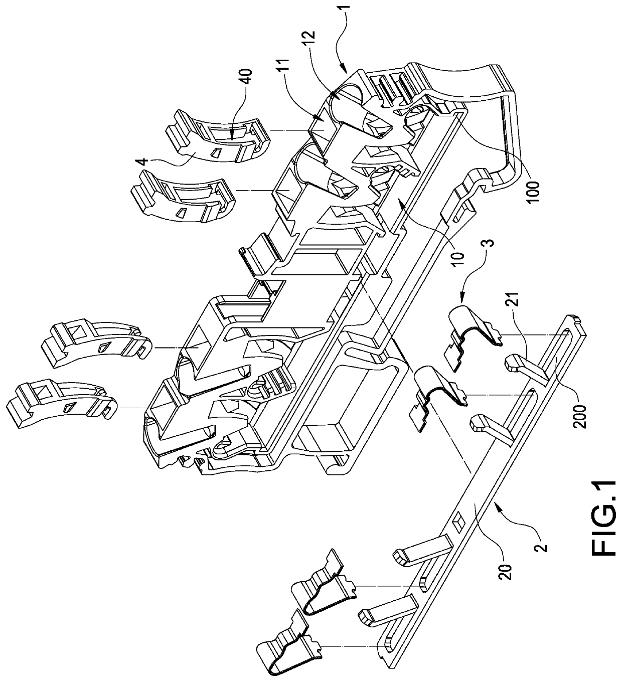
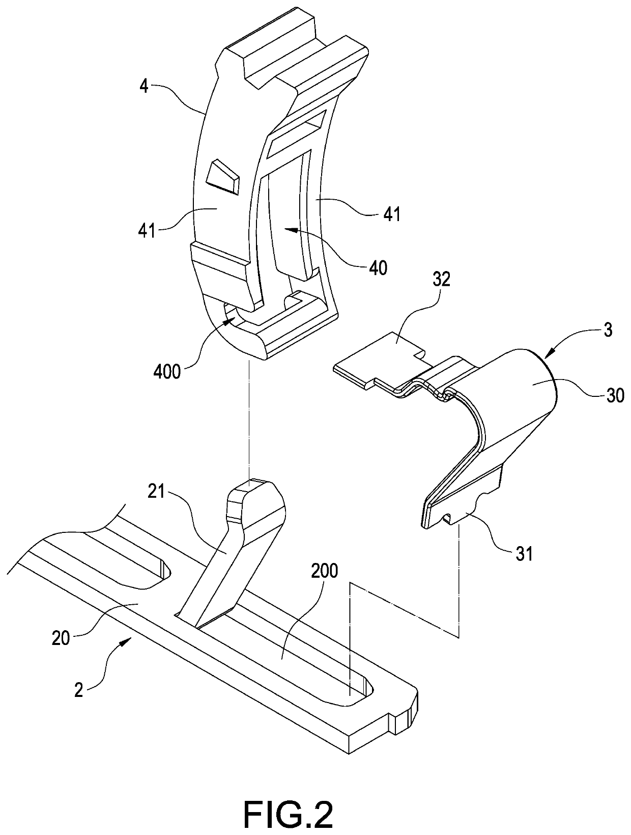
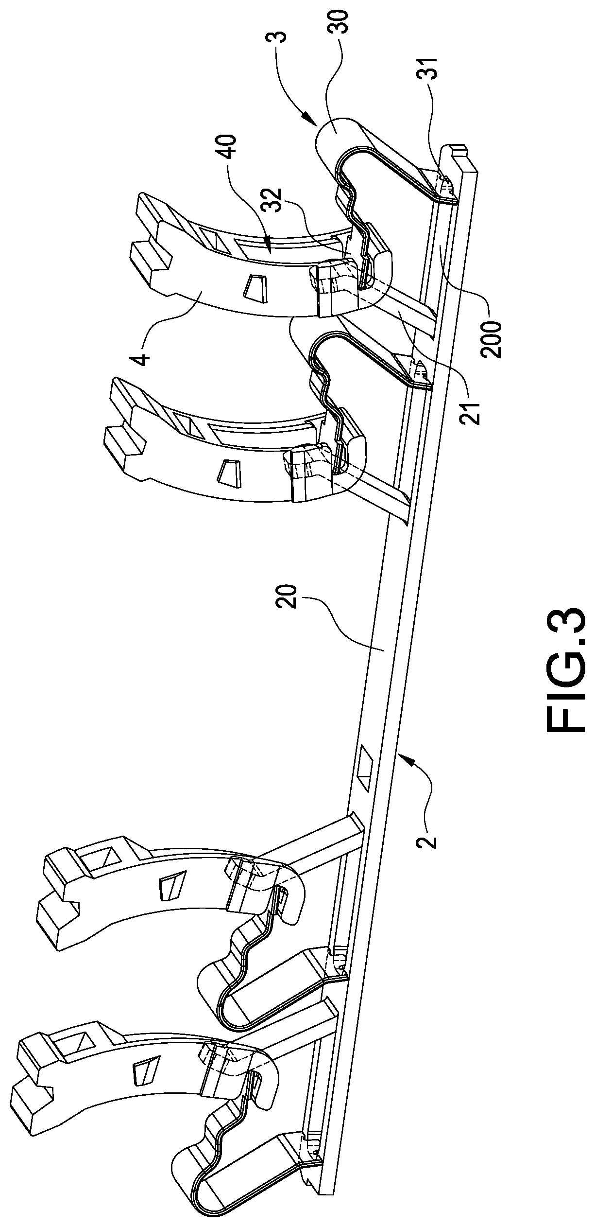
[0014]Please refer to FIG. 1, which is an exploded view of the invention. The invention provides an improved terminal block structure for being inserted by a wire 5 to make electric connection, which includes an insulative body 1, a conductive member 2, an elastic sheet 3 and a pressing member 4.

[0015]A size of the insulative body 1 can be varied depending upon the number of the wires 5 to be inserted. Also, both the elastic sheet 3 and the pressing sheet 3 can be increased depending upon the number of the wires 5. In the embodiment of the invention, the insulative body 1 is a long flat body and allows the wires 5 to be inserted into a longitudinal side thereof. For the sake of conciseness, only one wire is depicted. The insulative body 1 has a receiving room 10 therein. The receiving room 10 is formed in a side of the insulative body 1. The insulative body 1 is formed with a pressing hole 11 and a wire hole 12. The wire hole 12 is used to be inserted by the wire 5.

[0016]Please refe...


PUM


Abstract

A terminal block includes an insulative body, a conductive member, an elastic sheet and a pressing member. The insulative body has a receiving room therein and is formed with a pressing hole and a wire hole, which separately communicate with the receiving room. The conductive member is received in the receiving room and has a seat and a contact portion tilted up from the seat. The elastic sheet is received in the receiving room. An end of the elastic sheet is in contact with the conductive member. The pressing member is disposed in the pressing hole and capable of moving toward the receiving room to push another end of the elastic member. The pressing member has a placement slot. Each of two sides of the placement slot has a blocking wall.

Description

BACKGROUND OF THE INVENTIONTechnical Field[0001]The invention relates to electric connectors, particularly to an improved terminal block structure.Related Art[0002]A terminal block is an electric component used in machines or devices with requirements of connecting electric apparatuses. It can used to connect power cords, control lines or data transmission lines.[0003]Usually, a conventional terminal block is composed of a body and an elastic sheet assembled thereto. The body and the elastic sheet are assembled by riveting or engagement. Besides the elastic sheet or a conductive terminal, a metal cap is usually needed to prevent a wire from laterally escaping from the body when the wire is fixed. Thus, material and assembling costs will be increased. This is an issue to be solved.SUMMARY OF THE INVENTION[0004]An object of the invention is to provide an improved terminal block structure, which can fasten a wire by existing components without an additional cap to save manufacturing co...

Claims


Application Information

Patent Timeline
IPC IPC(8): H01R9/24H01R4/48H01R9/26H01R4/22H01R12/51
CPCH01R4/4836H01R4/4845H01R9/2416H01R4/22H01R9/24H01R4/4827H01R4/4818H01R12/515H01R9/2616H01R9/26H01R4/48455H01R4/48365H01R4/48185H01R4/48275
Inventor WU, SHANG-TSAI
Owner DINKLE ENTERPRISE
Why Eureka
Try Eureka