Valve component for regulating or controlling a fluid pressure

a valve component and fluid pressure technology, applied in the direction of diaphragm valves, engines/engines, machines/engines, etc., can solve the problems of leakage and escape of oil, damage to material properties, and pressure in the crankcase to rise, and achieve the effect of low noise developmen

Active Publication Date: 2020-09-29
MANN HUMMEL GMBH
View PDF14 Cites 0 Cited by
  • Summary
  • Abstract
  • Description
  • Claims
  • Application Information

AI Technical Summary

Benefits of technology

[0008]It is an object of the invention to provide a valve component for switching at low pressure differences which exhibits a low noise development when operated at an internal combustion engine.
[0009]The aforementioned object is solved according to an aspect of the invention by a valve component that comprises a unit for regulating or controlling a fluid pressure and further comprises an expansion chamber, wherein the unit comprises a valve housing, comprising a first housing part and a second housing part, between which a switching element is arranged, wherein the first housing part comprises an inlet and an outlet for a fluid, wherein the switching element is arranged between the inlet and the outlet for regulating, releasing or shutting off a flow of the fluid, wherein the switching element separates two chambers in the housing from each other, wherein, in open switching position of the switching element, inlet and outlet are connectable by means of one of the chambers, and wherein at least a first venting bore of the other one of the chambers opens into the expansion chamber. The expansion chamber comprises the same pressure as the other chamber connected with the expansion chamber and serves for noise minimization, wherein the expansion chamber does not affect the pressure difference at the switching element.

Problems solved by technology

These blow-by gases cause the pressure in the crankcase to rise, and leakages and escape of oil may be the result.
These gases attack many elastomer types whereby damages of the material properties may occur.
The components made of these materials become brittle, porous, and cracked.
When the switching films are damaged, the environmentally harmful blow-by gases directly reach the environment because the system is no longer seal-tight.
In the known pressure regulating valves, the switching diaphragm, depending on respective operating point and employed material of the switching diaphragm, may be excited to vibrate which leads to disruptive noises that moreover may propagate into the environment through the required venting bore in the cover of the pressure regulating valve.

Method used


Image

  • Valve component for regulating or controlling a fluid pressure
  • Valve component for regulating or controlling a fluid pressure

Examples


Embodiment Construction

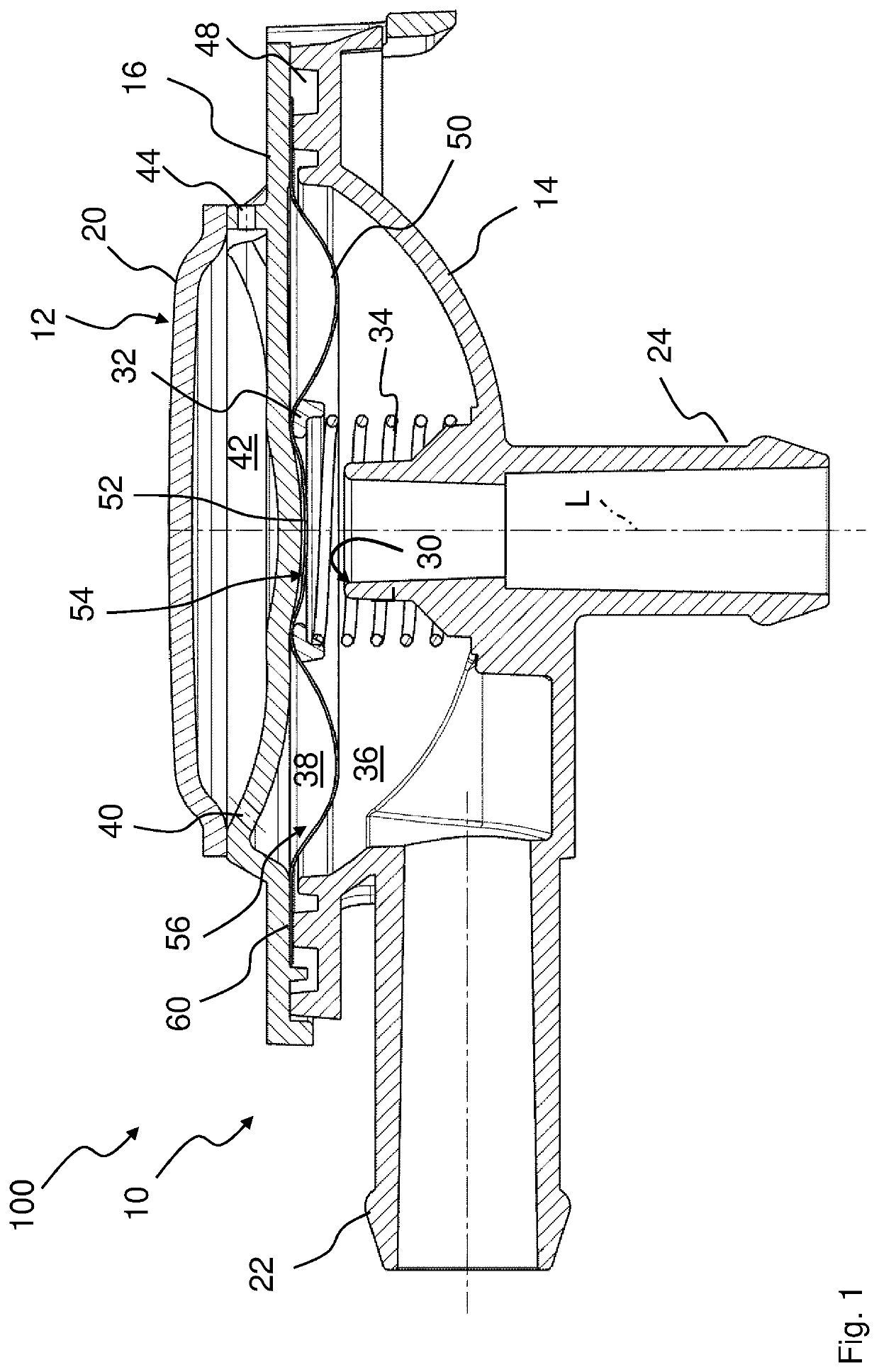
[0039]In the Figures, same or same-type components are identified with same reference characters. The Figures show only examples and are not to be understood as limiting.

[0040]FIG. 1 shows a section illustration of a first embodiment of a valve component 100 according to the invention. This embodiment is beneficial when housing parts 14, 16 of the valve component 100 are connected to each other by laser welding. The valve component 100 comprises a unit 10 for regulating or controlling a fluid pressure as well as at least one expansion chamber 42. The unit 10 comprises a valve housing 12 which comprises a first housing part 14 and a second housing part 16. The first housing part 14 comprises an inlet 22, which is embodied like a socket in an exemplary fashion, and an outlet 24, which is embodied like a socket in an exemplary fashion, for a fluid. Between the two housing parts 14, 16, an areal switching element 50 is arranged which is serving for regulating, releasing or shutting off ...


PUM


Abstract

A valve component is provided with a unit for regulating or controlling a fluid pressure and is further provided with an expansion chamber. The unit has a valve housing with a first housing part and a second housing part, between which a switching element is arranged. The first housing part has an inlet and an outlet for a fluid. The switching element is arranged between the inlet and the outlet for regulating, releasing or shutting of a flow of the fluid. The switching element separates two chambers in the valve housing from each other. In open switching position of the switching element, the inlet and the outlet are connected by one of the chambers, and at least one first venting bore opens from the other one of the chambers into the expansion chamber.

Description

BACKGROUND OF THE INVENTION[0001]The invention concerns a valve component for regulating or controlling a fluid pressure, in particular for the pressure regulation of the internal combustion engine and / or of the crankcase of the internal combustion engine of a motor vehicle.[0002]Pressure regulating valves are employed, for example, in the venting line between crankcase and the intake manifold of an internal combustion engine. In this context, the goal is to prevent the pressure or vacuum in the containers to be vented from rising beyond a predetermined value.[0003]In internal combustion engines, blow-by gases occur that are produced in that the combustion gases in the cylinder escape past the cylinder piston into the crankcase. These blow-by gases cause the pressure in the crankcase to rise, and leakages and escape of oil may be the result. In order to avoid a pressure increase and to discharge the blow-by gases in an environmentally friendly way, the blow-by gases are returned fro...

Claims


Application Information

Patent Timeline
Patent Type & Authority Patents(United States)
IPC IPC(8): F01M13/00F02F1/24
CPCF01M13/0011F02F1/24F01M2013/0016F16K7/17
Inventor BOCK, LUKASTILG, JUERGEN
Owner MANN HUMMEL GMBH
Why Eureka
Try Eureka