Assembly and method for mounting a pump bearing in/on plastic coolant pump housings

a technology of plastic coolant pump and bearing, which is applied in the direction of bearings, shafts, couplings, etc., can solve the problems of high temperature, large thermal stress on the pump bearing, and the bearing used as the pump bearing must demonstrate a relatively large bearing play, so as to achieve cost-effective and simple production technology, the effect of simple production and installation

Inactive Publication Date: 2013-06-11
NIDEC GPM GMBH
View PDF13 Cites 0 Cited by
  • Summary
  • Abstract
  • Description
  • Claims
  • Application Information

AI Technical Summary

Benefits of technology

[0026]The invention is therefore based on the task of developing an assembly that can be produced and installed in simple manner, as well as a method that is cost-advantageous and simple in terms of production technology, for mounting pump bearings in / on plastic coolant pump housings, which does not have the aforementioned disadvantages of the state of the art, allows tempering of the plastic housing and the use of bearings having little bearing play, as well as all the advantages that result from this, such as an increased useful lifetime, low noise development, stress relief of the shaft sealing ring, i.e. the rotating mechanical seal, and more, and furthermore guarantees bonding / adhesion strength between the pump bearing and the pump housing, over a large area and uniformly distributed, with minimal production and installation effort, at an optimal sealing gap geometry and a high degree of effectiveness of the pump, so that a great transfer of force from the pump bearing to the pump housing is guaranteed, without impairing the stability of the axle journal.

Problems solved by technology

This variant of attaching the bearing has the disadvantages that the pump bearing is exposed to temperatures of up to 300° C. and thereby subjected to very great thermal stress.
Aside from other increased production and installation effort connected with this, the coolant pumps having injection-molded pump bearings have the additional disadvantage that the bearings used as pump bearings must demonstrate relatively great bearing play, because of the twisting of the outer ring in the plastic, caused by the technology.
This great bearing play necessarily results in a great “unbalance,” which makes it more difficult to provide the shaft seal that must be taken over by the shaft sealing ring, increases the installation effort, reduces the useful lifetime of the bearing, and furthermore causes increased running noises.
Another disadvantage of coolant pumps having a bearing injection-molded into the plastic housing is that these plastic housings cannot be tempered as a result of the integrated pump bearings, because the plastic is heated to 180° C. to 200° C. during tempering, so that the non-tempered plastics necessarily have a lesser strength as compared with tempered plastics.
Furthermore, it is not possible to separate the steel bearings injection-molded in from the plastic of the housing without destroying the housing, so that re-use of the bearing housings is precluded.
Furthermore, recycling of plastic housings having pump bearings injection-molded in is very cost-intensive, since separation of the bearings injection-molded in from the plastic of the housing necessarily requires an increased expenditure of time and / or labor.
However, these production and installation tolerances that are necessarily required for the required adhesive gap significantly influence the sealing gap geometry between the impeller wheel and the related housing bore, and increase the leakage flow as a significant influence variable for the degree of effectiveness of the coolant pump, so that in the case of coolant pumps having pump bearings glued in (at justifiable production and / or installation effort), either only slight bearing stresses can be transferred to the pump housing, or the adhesive gaps are designed in such a manner that great bearing stresses can be transferred to the pump housing.
However, these coolant pumps last mentioned then necessarily have a low degree of effectiveness.
However, this construction, which has already proven itself in practice, requires increased production effort for the production of the “adhesive ring,” since the circumferential housing grooves and the bores required for “filling of these housing grooves” have to be mechanically made in the plastic housings subsequently, for the “production” of the adhesive ring.
The radial housing groove to be disposed in the plastic housing of the coolant pump brings about the result that the axle journal is weakened by the placement of this housing groove, so that under extreme belt loads, there is the risk of fracture at this location.
On the other hand, injection of the polyamide, by way of the inlet bore, into the ring-shaped interstice formed by housing groove and bearing groove, requires precise metering of the injection amount and, at the same time, precise monitoring of the filling process, since the polyamide can flow off axially in the direction of the shaft sealing ring, for example, and this can result in impairment of the ability of the radial sealing ring, i.e. the rotating mechanical seal, to function properly, among other things, or can cause incomplete filling of the ring groove, clearly restricting the desired axial and radial securing of the bearing in the plastic housing.
The placement of crosspieces in the bearing bore of the plastic housing, with crosspiece grooves lying between them, which was proposed in connection with the inlet bore and the housing groove in the dependent claims of the aforementioned application, did not result in the desired strength of the adhesive connection in practical implementation, however, since it was not possible to guarantee complete filling of the ring groove and the crosspiece grooves by the viscous adhesive.

Method used


Image

  • Assembly and method for mounting a pump bearing in/on plastic coolant pump housings
  • Assembly and method for mounting a pump bearing in/on plastic coolant pump housings
  • Assembly and method for mounting a pump bearing in/on plastic coolant pump housings

Examples


Embodiment Construction

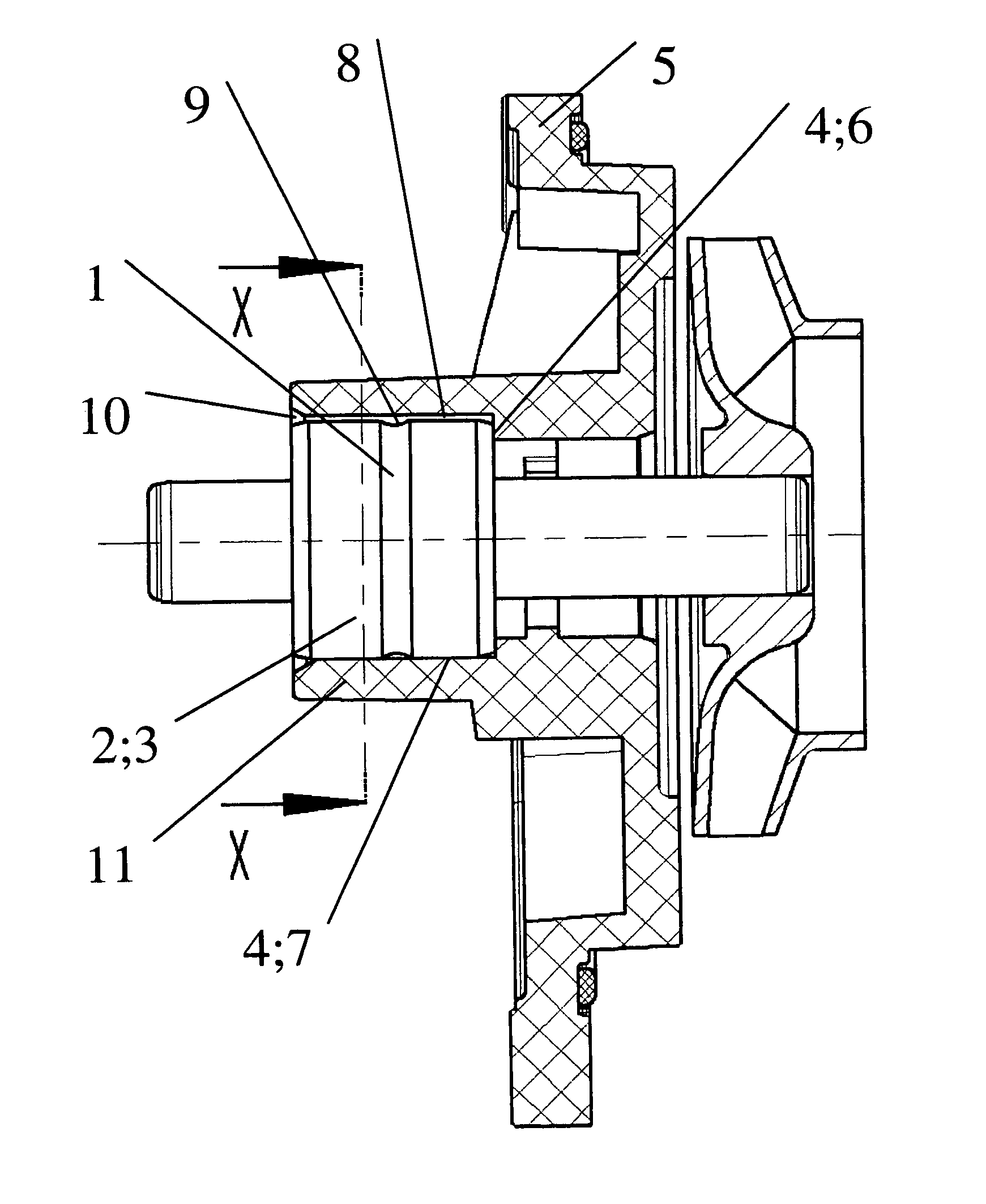
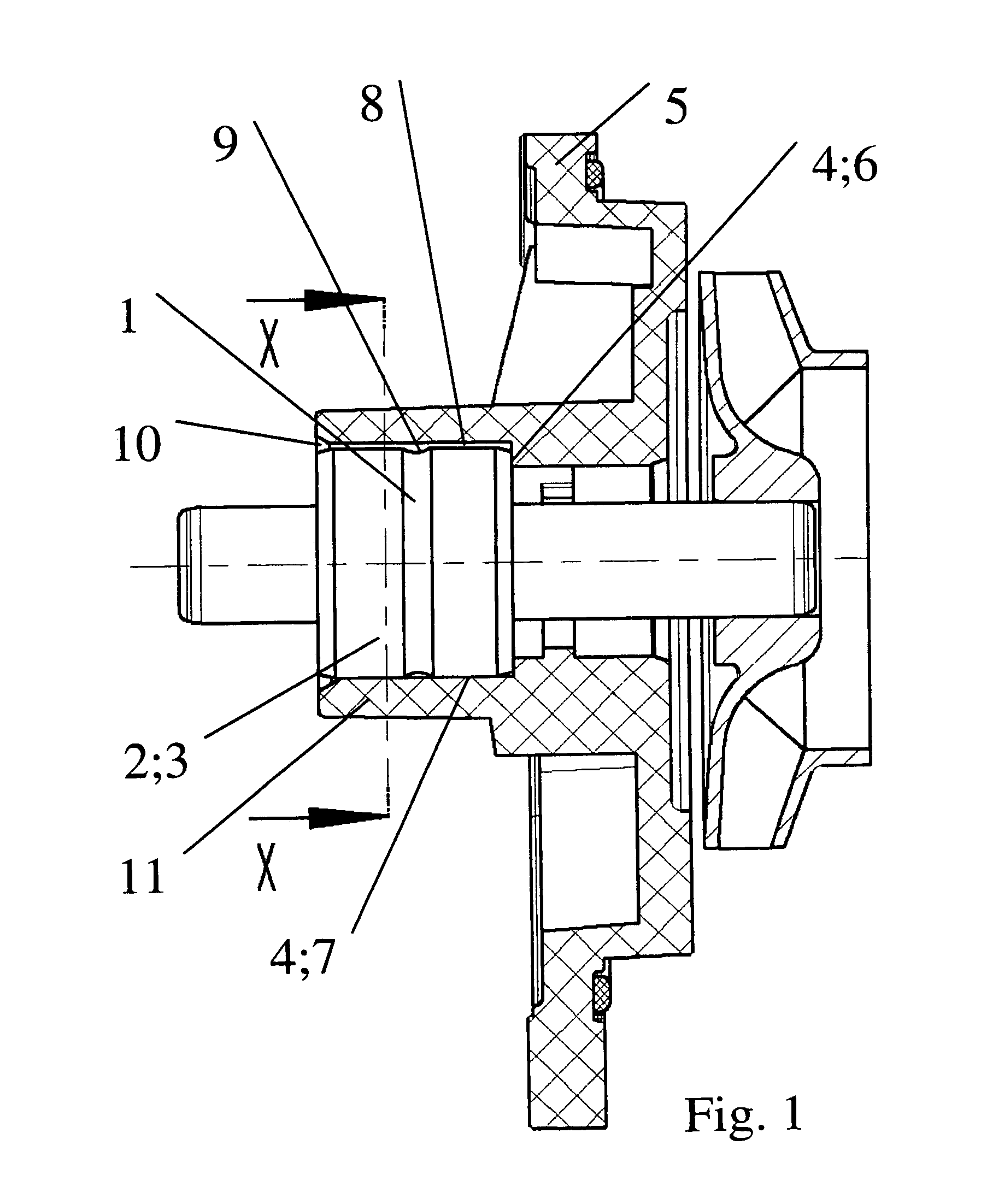
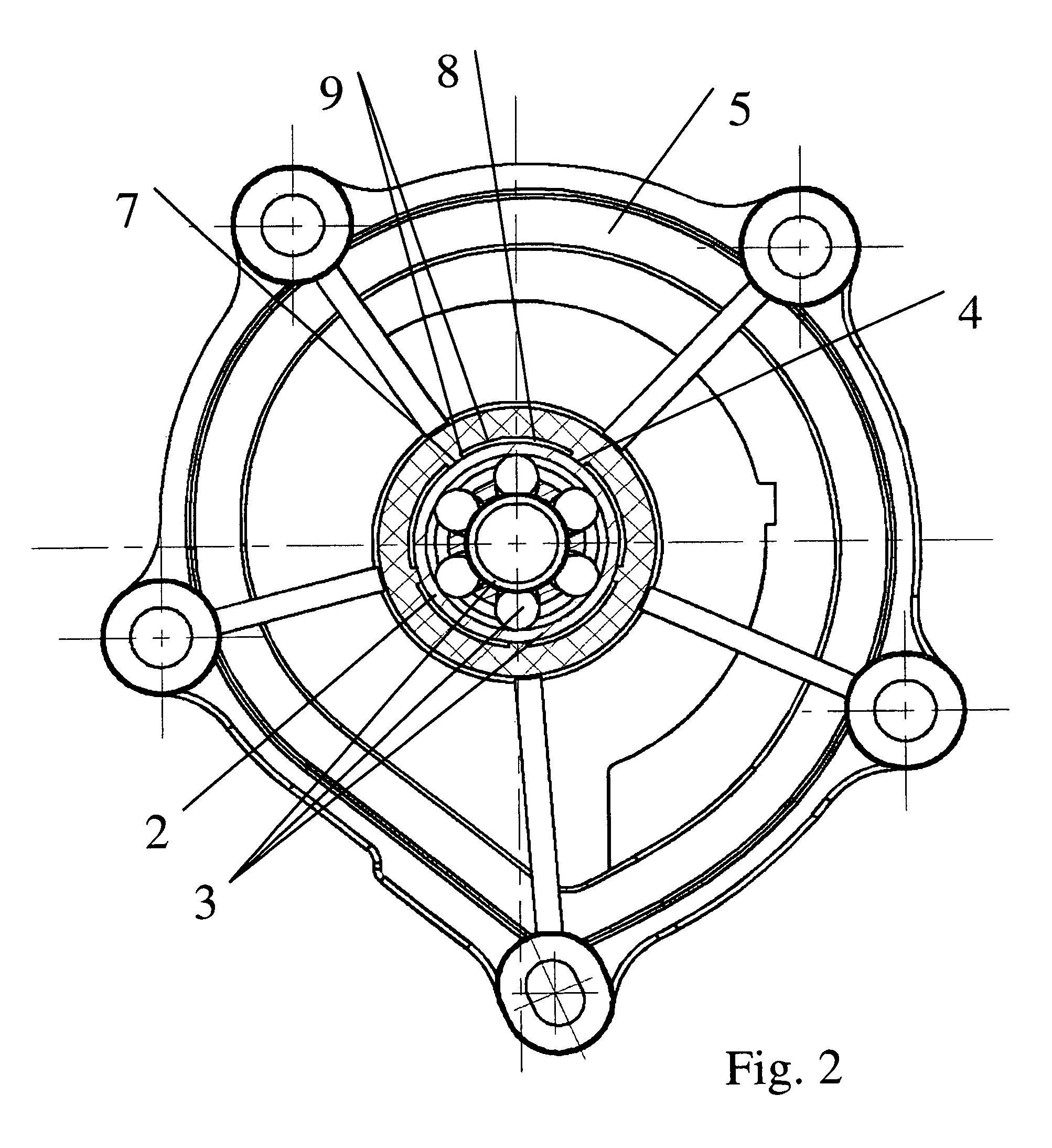
[0053]FIG. 1 shows one of the possible constructions of the assembly according to the invention in a side view, in section. FIG. 2 shows the related section at X-X, according to FIG. 1.

[0054]In this connection, a bearing ring 2 provided with at least one bearing ring groove 1, of a pump bearing 3, is disposed in a bearing seat 4 of a plastic coolant pump housing 5. The bearing seat 4 is formed by several positioning crosspieces 7 in connection with an axial bearing collar 6.

[0055]Adhesive grooves 8 that are separated from one another, i.e. separate, are disposed between the positioning crosspieces 7 and the bearing collar 6; they are provided with liquid-tight walls (9) in four of the axial directions, in each instance, i.e. they have no connection channels among each other.

[0056]Only above these adhesive grooves 8, i.e. in the region of the bearing ring 2 of the pump bearing 3 to be disposed there, and furthermore at the outer edge of the pump bearing 3, in the region of the slot-s...


PUM

PropertyMeasurementUnit
depthaaaaaaaaaa
depthaaaaaaaaaa
temperaturesaaaaaaaaaa

Abstract

The assembly includes a pump bearing ring that is fitted with at least one bearing groove and is disposed in / on a bearing seat of a plastic coolant pump housing with an axial bearing collar, and several positioning webs which are located on the bearing seat. Separate adhesive grooves are placed between the positioning webs and the bearing collar. The adhesive grooves are provided with liquid-tight walls in four of the axial directions, an opening in the direction of the pump bearing ring, and slot-shaped adhesive pockets in the area of the outer edge of the pump bearing. A method for mounting a pump bearing in / on a plastic coolant pump housing includes steps of spreading adhesive on a bearing ring, pressing the bearing ring into / onto the bearing seat, and inductively heating the pump bearing in the plastic coolant pump housing.

Description

CROSS REFERENCE TO RELATED APPLICATIONS[0001]Applicants claim priority under 35 U.S.C. §119 of German Application No. 10 2005 030 424.9 filed Jun. 30, 2005. Applicants also claim priority under 35 U.S.C. §365 of PCT / DE2006 / 001010 filed Jun. 13, 2006. The international application under PCT article 21(2) was not published in English.BACKGROUND OF THE INVENTION[0002]1. Field of the Invention[0003]The invention relates to an assembly and a method for mounting a pump bearing in / on plastic coolant pump housings.[0004]2. The Prior Art[0005]In the prior art, coolant pumps having plastic housings are previously described.[0006]In the case of these designs, the pump bearing is positioned into an injection-molding die before injection molding, and integrated into the plastic housing, in a secure position, during injection molding.[0007]This variant of attaching the bearing has the disadvantages that the pump bearing is exposed to temperatures of up to 300° C. and thereby subjected to very gre...

Claims


Application Information

Patent Timeline
Patent Type & Authority Patents(United States)
IPC IPC(8): F16C43/00B21D53/10
CPCF04D29/026F04D29/0462F04D29/049F04D29/628F16D1/068F16C35/067Y10T29/49696F16C2360/42Y10T29/49236Y10T29/49703F05D2300/43F16C2360/44F16C2226/40
Inventor SCHMIDT, EUGENBLAUROCK, FRANKLEUSENRINK, HARTMUT
Owner NIDEC GPM GMBH
Why Eureka
Try Eureka