Valve for a water-supply system

a valve and water supply technology, applied in the field of valves, can solve the problems of impaired function, fluid valve clogging with impurities, limited liquid flowing through the fluid valve, etc., and achieve the effect of stable and advantageous operating parameters

Inactive Publication Date: 2019-06-25
FRANZ KALDEWEI GMBH & CO KG
View PDF12 Cites 0 Cited by
  • Summary
  • Abstract
  • Description
  • Claims
  • Application Information

AI Technical Summary

Benefits of technology

[0015]Another object is the provision of such an improved valve, in particular for a bathwater circulating system that overcomes the above-given disadvantages, in particular that is characterized by high operational security and low maintenance requirements.
[0056]Within the framework of the invention, preferably a centrifugal pump is provided as pump. The pump is to be chosen such that, at the lowest possible cost and a low development of noise, a good thorough mixing of the drawn-out bathwater and aspirated ambient air is achieved.

Problems solved by technology

As a result, a pressure differential is present between the inlet and the outlet and the amount of liquid flowing through the fluid valve is limited.
When using the fluid valve as a pressure-reducing valve in a plumbing system, there is a risk that the fluid valve becomes clogged up with impurities and will become impaired in its function thereby.
A similar risk of clogging with impurities is present also in other applications.

Method used


Image

  • Valve for a water-supply system
  • Valve for a water-supply system
  • Valve for a water-supply system

Examples


Embodiment Construction

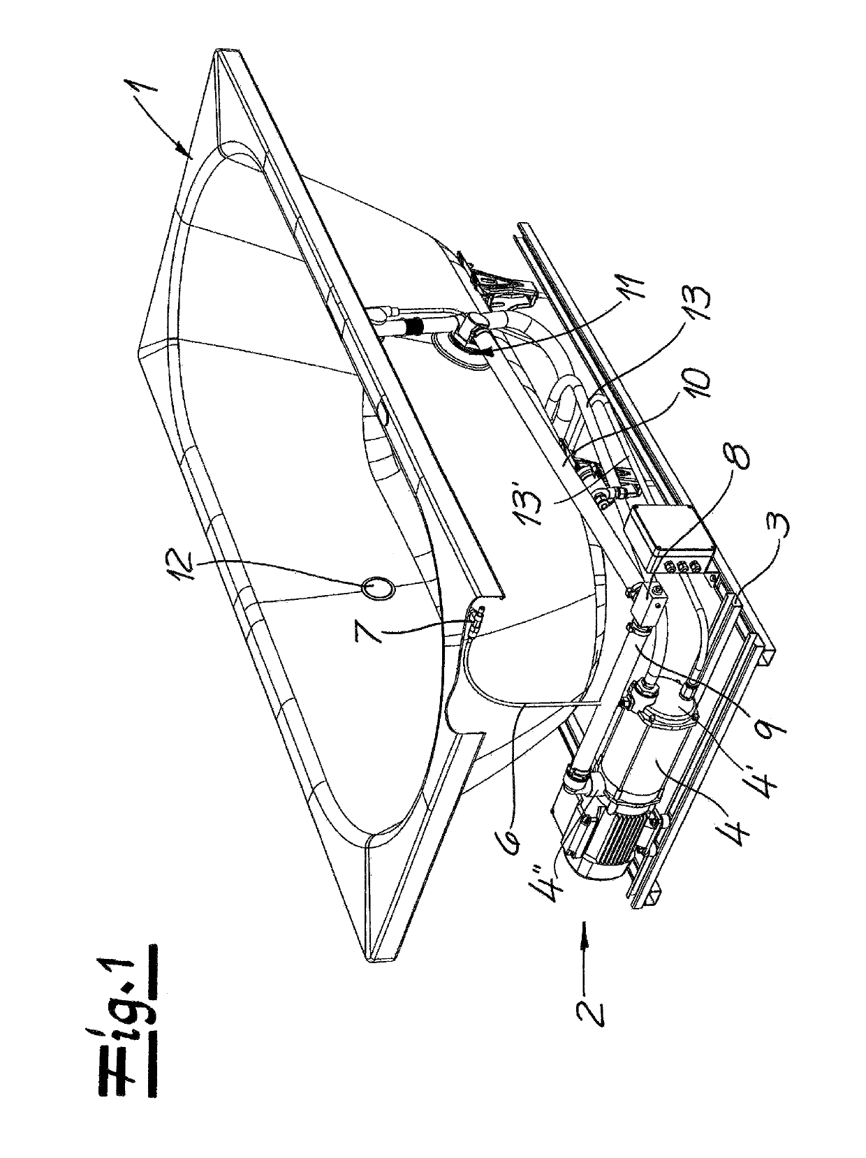
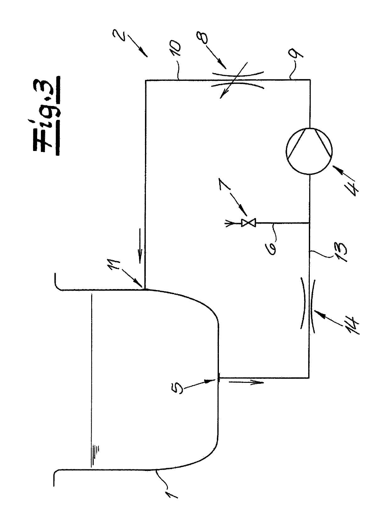
[0074]As seen in FIG. 1, a bathtub 1 sitting on a base 3 has a bathwater circulating system 2 that circulates bathwater through the bathtub 1. This bathwater is provided according to the invention with small bubbles in order to increase well-being for a user and achieve a positive influence on the skin of a user.

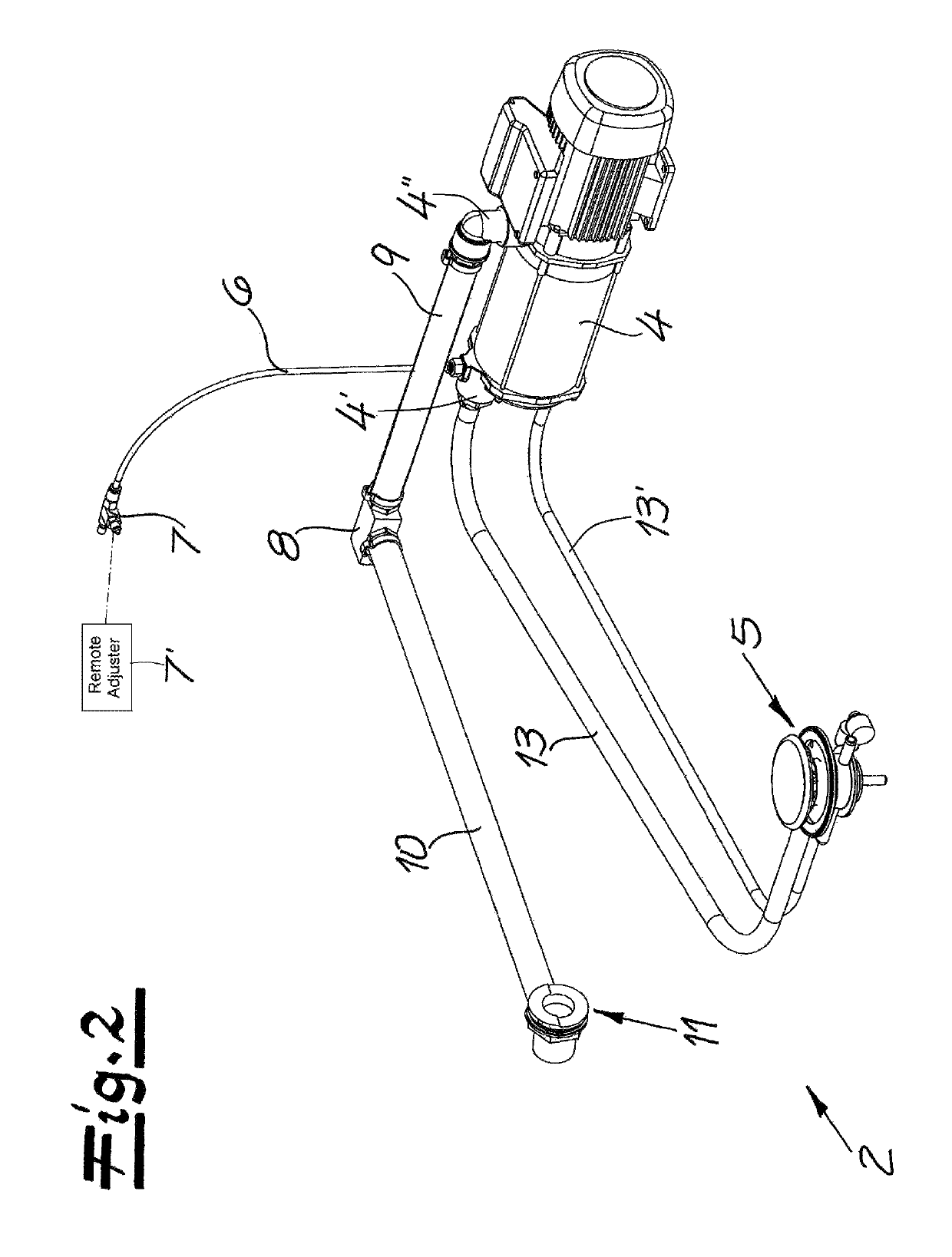
[0075]FIGS. 1 and 2 show how a centrifugal pump 4 having an intake port 4′ and an output port 4″ draws bathwater out of the tub 1 through a floor drain 5 connected to the intake port 4′. An air-supply conduit 6 having an intake valve 7 is also connected to the intake port 4′. An intake valve 7 at an upstream end of the air-supply conduit 6 is below an upper edge of the tub 1, and is preferably a needle valve that makes possible a precise dosing of the ambient air that is drawn in there. Preferably, the intake valve 7 can be adjusted directly by hand or with a tool, and it is normally protected by an inspection flap or a cover, or can also be mounted to be freely accessible. ...


PUM

PropertyMeasurementUnit
pressureaaaaaaaaaa
pressureaaaaaaaaaa
lengthaaaaaaaaaa

Abstract

A valve for a plumbing system has a housing with an inlet and an outlet and a valve body movable in the housing between a throttle position with a decreased a flow cross section and reduced flow between the inlet and outlet and an open position with a large flow cross section and free flow between the inlet and outlet. Structure in the valve body applies hydraulic pressure from the inlet or outlet to the valve body to shift same into the throttle position when a pressure differential between the inlet and the outlet exceeds a specified value and into the open position in the absence of a pressure differential between the inlet and the outlet.

Description

FIELD OF THE INVENTION[0001]The present invention relates to valve. More particularly this invention concerns such a valve used in a bathwater circulating system.BACKGROUND OF THE INVENTION[0002]A fluid valve such as usable in a household plumbing system typically has a housing with an inlet and an outlet, and a valve body is fed so as to move longitudinally within the housing. In practice, such fluid valves are used for varying a flow cross section of a fluid passage.[0003]The present invention specifically relates to a fluid valve whose flow cross section is reduced in a throttle or flow-impeding position, so that on flow through the valve a pressure drop results between the inlet and the outlet. As a result, a pressure differential is present between the inlet and the outlet and the amount of liquid flowing through the fluid valve is limited.[0004]Consequently, within the context of the invention, the term pressure differential between the inlet and the outlet refers to a higher ...

Claims


Application Information

Patent Timeline
Patent Type & Authority Patents(United States)
IPC IPC(8): B01F13/04F16K17/30B01F5/12B01F15/02B01F3/04B01F5/10G05D7/01A61H33/02A61H33/00B01F35/60B01F25/60
CPCB01F13/042A61H33/02B01F3/0446B01F3/04503B01F5/106B01F5/12F16K17/30G05D7/0133B01F15/0258A61H2201/50A61H2033/0033A61H2033/021A61H2033/022A61H2033/023A47K3/00F16K31/1223F16K31/12F16K41/04E03C1/04F16K17/22B01F23/2323B01F25/53B01F35/718F16K1/00B01F35/602B01F23/232B01F25/60B01F23/2326
Inventor SCHMIDT, THOMASMEYER, TOBIAS
Owner FRANZ KALDEWEI GMBH & CO KG
Why Eureka
Try Eureka