
Rotary actuator

Active Publication Date: 2020-10-13
SIEMENS AG
View PDF19 Cites 0 Cited by
  • Summary
  • Abstract
  • Description
  • Claims
  • Application Information

AI Technical Summary

Benefits of technology

The present invention provides a rotary actuator that can reliably transmit switching positions over a long service life. The actuator has a guide element that securely attaches to the actuating handle, allowing for direct transmission of movement to the crown. This results in a compact and stable functional unit that can achieve a defined latching position, leading to better switching sensation and a long service life.

Problems solved by technology

In particular with rotary actuators there can be a problem that the mechanical transmission chain of the rotational actuation is disrupted starting from the actuating handle, and as a result the defined latching position and therefore switching position is not reached but, owing to incorrect mechanical transmission, only an intermediate position is reached which does not correspond to the desired switching position state.

Method used


Image

  • Rotary actuator
  • Rotary actuator

Examples


Embodiment Construction

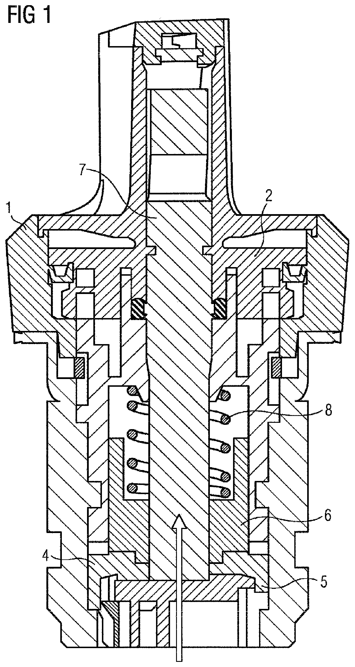
[0023]FIG. 1 shows a rotary actuator according to the invention having a cylindrical main body 1 and an actuating handle 2 which is fitted onto the cylindrical main body 1 and has a display area which can preferable be illuminated. The actuating handle 2 is mounted here in a rotatable fashion in the cylindrical main body 1 of the rotary actuator. An inserted base 4, which engages by means of latching hooks 5 in corresponding contours of the inner surface of the cylindrical main body 1 of the rotary actuator and is as a result installed in a positionally stable fashion is positioned in the cylindrical main body 1 of the rotary actuator. The inserted base 4 engages with its contours in corresponding contours of a crown 6. A guide element 7, in particular a lightguide, which is guided by the crown 6 which is preferably embodied in a cylindrical fashion is arranged between the inserted base 4 and actuating handle 2. A spring element 8, which permits resetting of the actuating handle 2 i...


PUM


Abstract

A rotary actuator includes a cylindrical main body, an actuating handle placed on the cylindrical main body and having a display area, a crown, and an inserted base which is arranged in the cylindrical main body and has contours which engage in contours of the crown. The rotary actuator further includes a guide element for guiding the inserted base and the crown.

Description

CROSS-REFERENCES TO RELATED APPLICATIONS[0001]This application is the U.S. National Stage of International Application No. PCT / EP20151077724, filed Nov. 26, 2015, which designated the United States and has been published as International Publication No. WO 2016 / 096360 A1 which claims the priority of German Patent Application, Serial No. 102014226618.1, filed Dec. 19, 2014, pursuant to 35 U.S.C. 119(a)-(d).BACKGROUND OF THE INVENTION[0002]The invention relates to a rotary actuator having a cylindrical main body and an actuating handle which is fitted onto the cylindrical main body and has a display area.[0003]Such rotary actuators are generally used to input commands at so-called machine / human interfaces. In this context, it is conceivable to use rotary actuators not only for switching control currents but also for power switching operations in that the rotary actuator is used as a trigger for power switches. Stringent requirements in terms of service life, robustness, seal of the el...

Claims


Application Information

Patent Timeline
IPC IPC(8): G05G5/06G05G1/10G05G5/05H01H19/635H01H19/02H01H19/00H01H19/36H01H3/42F21V8/00
CPCG05G5/06G05G5/05H01H19/6355G05G1/105G02B6/0001H01H3/42H01H2019/008H01H19/025H01H19/36
Inventor FAURIE, JEAN JACQUES
Owner SIEMENS AG
Learn More