Hydraulic fracture analysis

a fracture analysis and hydrostatic technology, applied in the field of hydrostatic fracture analysis, can solve the problems of inability to continuously measure the dts and inability to run a well, and achieve the effects of reducing the temperature effect of crossflow and other anomalies, improving signal size, and less nois

Active Publication Date: 2020-10-20
CONOCOPHILLIPS CO
View PDF105 Cites 2 Cited by
  • Summary
  • Abstract
  • Description
  • Claims
  • Application Information

AI Technical Summary

Benefits of technology

[0019]FIG. 2A illustrates the effect of measuring temperature early on versus later during shut-in. By waiting to measure for days or weeks to measure temperature, the changes in temperature are still observed. The signal may not be as big, but there is less noise. The effect is also much longer lasting than previously thought in the industry.
[0025]A “shut-in” is when a well is closed and no flow to the surface is allowed. Thus, fluids are not flowing in either direction, although there can be localized fluid movement at the very beginning of the shut-in from high to low pressure zones. Shut-in is performed for all kinds of reasons, including to control the well, to perform certain maintenance work, and the like. Herein, we obtain DTS temperature profiles during a postfrack period of shut-in to minimize flow effects and other anomalies, thus reducing noise in the temperature profile.
[0026]As used herein, “warmback” refers to the gradual warming of the temperature near a wellbore after injection of a frack fluid that is cooler than the reservoir. The “warmback period” is the time needed for the temperature to return to pre-injection levels. We have discovered herein, that the “warmback period” lasts much longer than previously thought, and that later measurements of temperature—days, weeks and even months after fracturing—still provide valuable information about the reservoir, and with less noise. Thus, the method requires that warmback not be measured immediately after injection ceases, but after a certain wait period of at least 36 hours, or 1 week, 1 month or more. This is called “postfrack” herein.

Problems solved by technology

It is not possible to run a well just for DTS—typically there are time constraints on taking DTS measurements and one cannot measure the DTS constantly.

Method used


Image

  • Hydraulic fracture analysis
  • Hydraulic fracture analysis
  • Hydraulic fracture analysis

Examples


Embodiment Construction

[0054]Reference will now be made in detail to embodiments of the present invention, one or more examples of which are illustrated in the accompanying drawings. Each example is provided by way of explanation of the invention, not as a limitation of the invention. It will be apparent to those skilled in the art that various modifications and variations can be made in the present invention without departing from the scope or spirit of the invention. For instance, features illustrated or described as part of one embodiment can be used in another embodiment to yield a still further embodiment. Thus, it is intended that the present invention cover such modifications and variations that come within the scope of the appended claims and their equivalents.

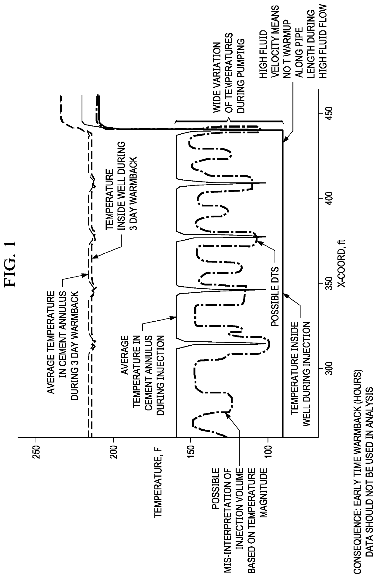
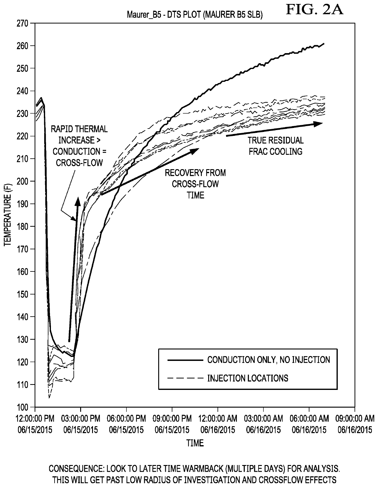
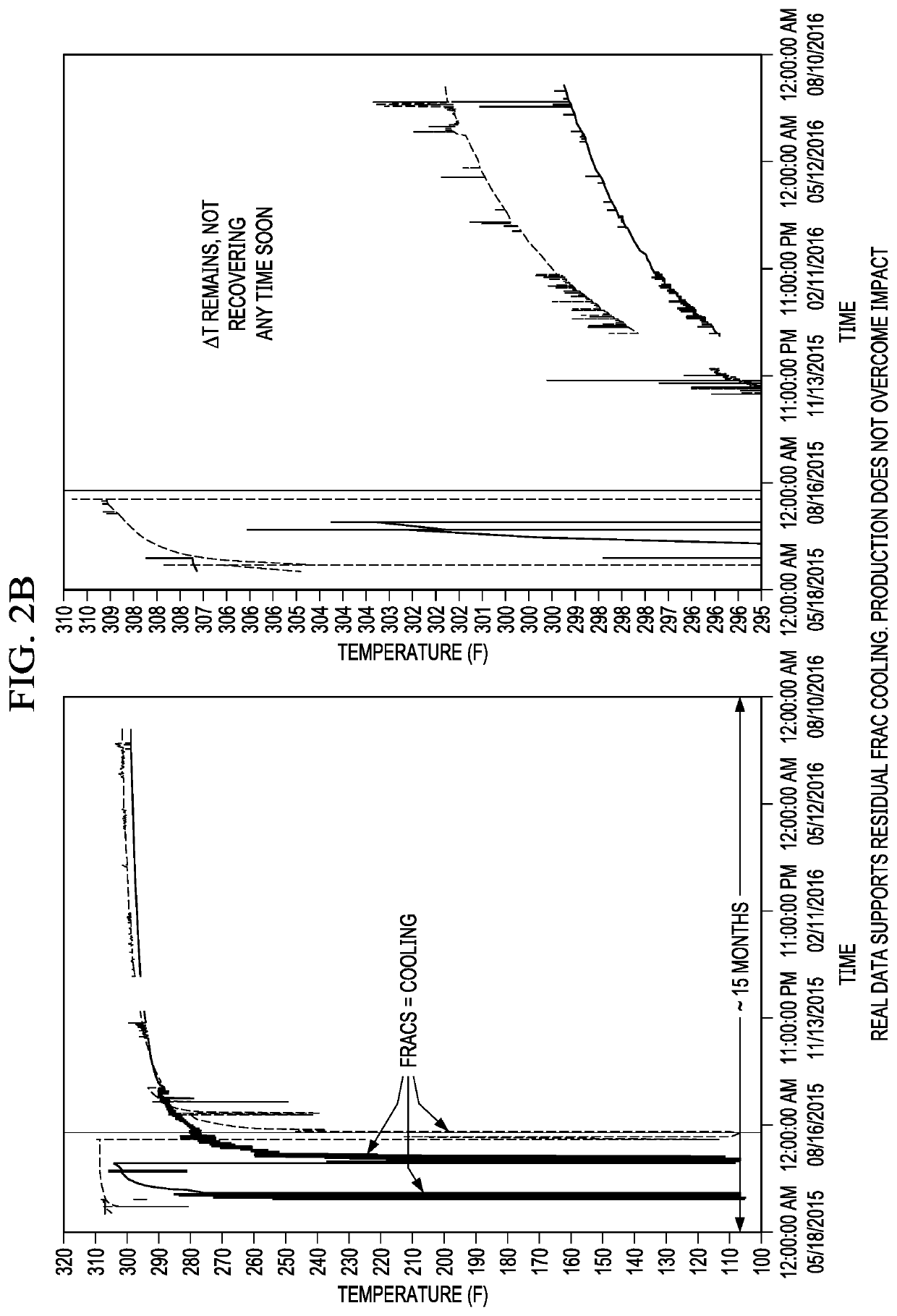
[0055]The temperature of injection fluid is typically lower than the temperature of each of the layers of the formation. Throughout the injection period, the colder fluid removes thermal energy from the wellbore and surrounding areas of the ...


PUM


Abstract

This disclosure describes a method of assessing fractures in an underground formation using temperature profile measured by a DTS. The fractures can be identified by a temperature profile established by the feedback signals obtained from the DTS, but the DTS measurements are made at least 36 hours after a stage is fractured and during shut-in, thus allow crossflow and other noise sources to abate. Further, the size of the temperature differential is indicative of fracture spacing or density, not volume of fluid flow as thought in the prior art. Thus, these methods can be used to optimize the next stage or next well in a fracturing program.

Description

PRIOR RELATED APPLICATIONS[0001]This invention is a continuation-in-part of and claims priority to U.S. patent Ser. No. 14 / 263,271, filed on Apr. 28, 2014, which is a non-provisional application of US 61 / 829,374, filed on May 31, 2013, each of which is incorporated by reference in its entirety herein for all purposes.FIELD OF THE INVENTION[0002]This invention relates to a system and method for identifying the presence of fractures in a wellbore during and after treatment, and more specifically to a system and method for assessing one or both of fracture density and fracture position in a wellbore after hydraulic fracturing treatment.BACKGROUND OF THE INVENTION[0003]Hydraulic fracturing, matrix acidizing, and other types of stimulation treatments are routinely conducted in oil and gas wells to enhance hydrocarbon production. The wells being stimulated often include a large section of perforated casing or an open borehole having significant variation in rock petrophysical and mechanic...

Claims


Application Information

Patent Timeline
Patent Type & Authority Patents(United States)
IPC IPC(8): E21B43/26E21B47/12E21B47/07
CPCE21B47/07E21B47/135E21B43/26G01V2210/646G01V2210/66
Inventor FRIEHAUF, KYLE
Owner CONOCOPHILLIPS CO
Why Eureka
Try Eureka