Quenching apparatus

a technology of quenching apparatus and cooling gas, which is applied in the direction of heat treatment apparatus, furnaces, manufacturing tools, etc., can solve the problems of deteriorating unfavorable quenching process, and flow of cooling gas, so as to improve the quality of treated products, the quenching process may be faster, and the effect of quick reversed flow

Active Publication Date: 2020-10-27
CHUNG WON KI
View PDF7 Cites 0 Cited by
  • Summary
  • Abstract
  • Description
  • Claims
  • Application Information

AI Technical Summary

Benefits of technology

[0018]According to the quenching apparatus of the present invention, the quenching process may be more quickly performed by quickly reversing the flow of the cooling gas flowing in the chamber by the simple operation.

Problems solved by technology

However, the flow of the cooling gas acts as a serious factor in the quenching process.
However, in the above Patent Document 1, the cooling gas flows only in the same direction and thus the treated product is not cooled uniformly, which causes the problem in that the quenching is not smoothly performed and the quality of the treated product deteriorates.

Method used


Image

  • Quenching apparatus
  • Quenching apparatus
  • Quenching apparatus

Examples


Embodiment Construction

[0024]A quenching apparatus according to an exemplary embodiment of the present invention will be described in more detail in order to assist in understanding of the features of the present invention.

[0025]It is to be noted that in adding reference numerals to elements of each accompanying drawing, like reference numerals refer to like elements even though like elements are shown in different drawings. Further, in describing exemplary embodiments of the present invention, when it is determined that detailed description of known functions or configuration may obscure the gist of the present invention, the detailed description will be omitted.

[0026]Hereinafter, exemplary embodiments of the present invention will be described in detail with reference to the accompanying drawings.

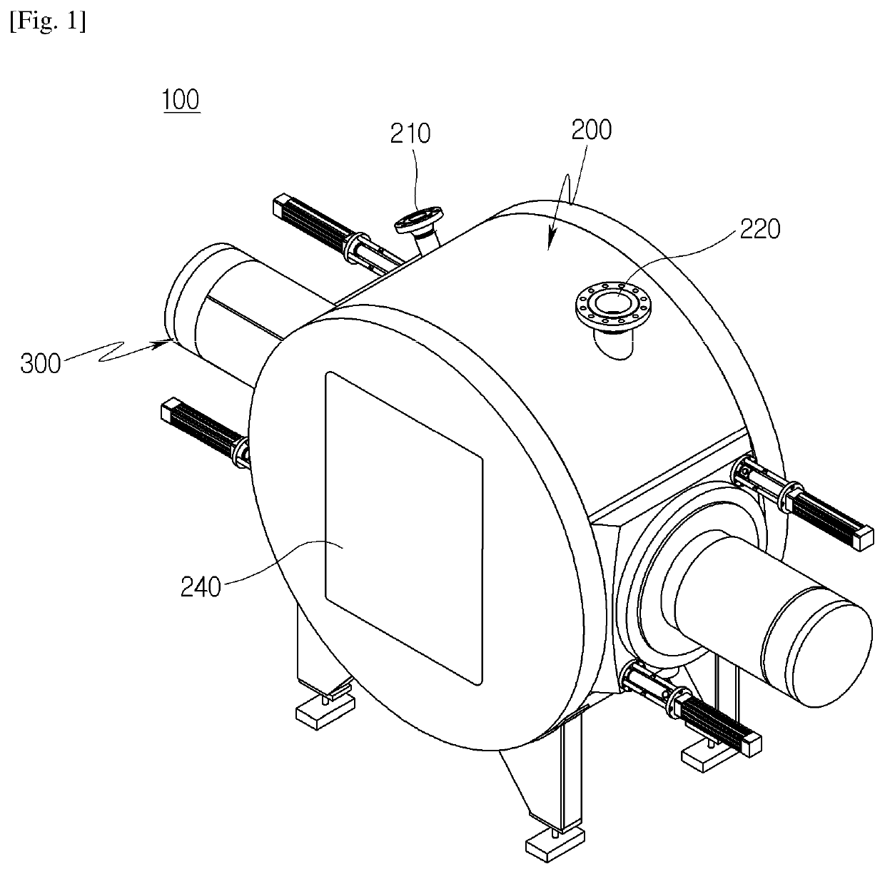
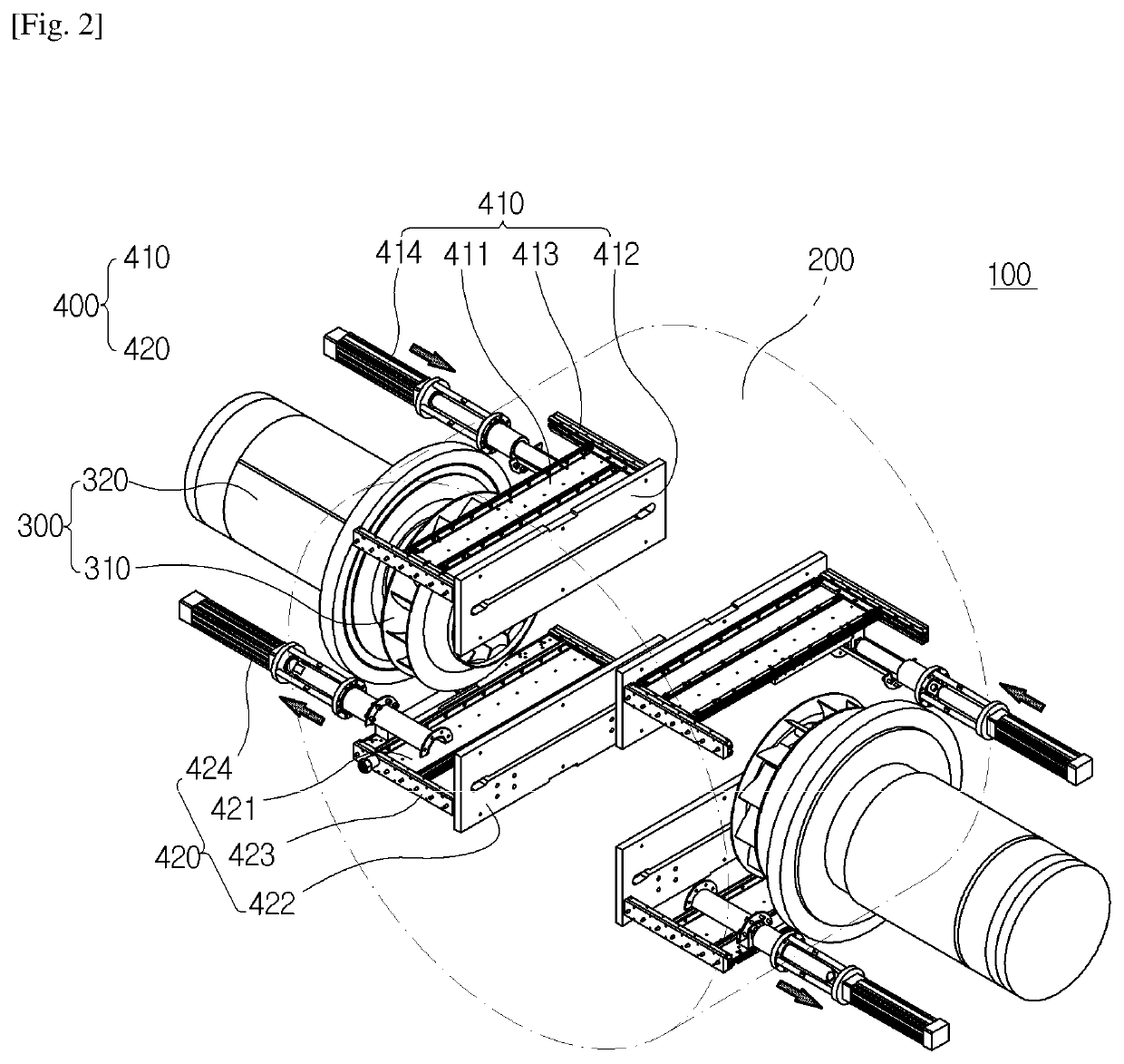
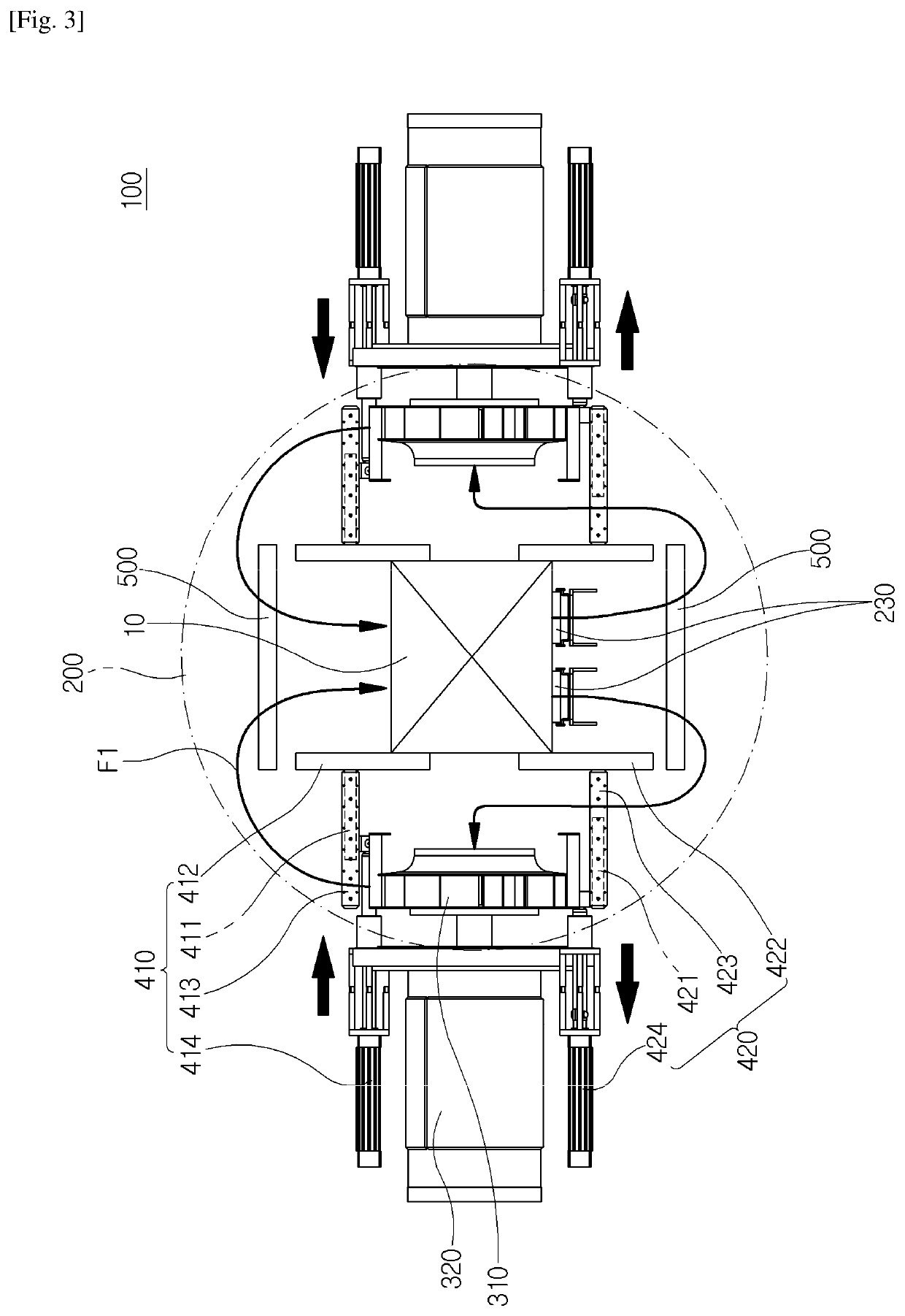
[0027]FIG. 1 is a perspective view schematically illustrating a quenching apparatus according to an embodiment of the present invention, FIGS. 2 and 3 are a perspective view and a side view schematically illust...


PUM

PropertyMeasurementUnit
temperatureaaaaaaaaaa
centrifugal forceaaaaaaaaaa
thicknessaaaaaaaaaa

Abstract

A quenching apparatus capable of quickly reversing a flow of cooling gas flowing in a chamber. The quenching apparatus includes: a chamber provided with a gas inlet and a gas outlet and having an object charged therein; a pair of flow generating means disposed on both sides of the chamber and generating a flow of gas in the chamber; and a flow direction reversing means disposed in the chamber and reversing a flow direction of gas to make the gas flow in any one of a first flow direction in which the gas flows from top to bottom of the object and a second flow direction in which the gas flows from the bottom to the top of the object.

Description

CROSS-REFERENCE TO RELATED APPLICATIONS[0001]This application is a 371 U.S. National Stage of International Application No. PCT / KR2017 / 001723, filed Feb. 16, 2017, which claims the benefit of and priority to Korean Patent Application No. 10-20160182374, filed Dec. 29, 2016. The entire disclosures of the above applications are incorporated herein by reference.TECHNICAL FIELD[0002]Exemplary embodiments of the present invention relate to a quenching apparatus, and more particularly, to a quenching apparatus capable of quickly reversing a flow of cooling gas flowing in a chamber.BACKGROUND ART[0003]Generally, a vacuum carburizing method has been successfully evaluated in terms of economic efficiency and quality improvement by remarkably shortening a carburizing time and securing uniformity of a carburizing layer. The vacuum carburization which is a high temperature carburizing process carried out under vacuum is usually performed at a high carburizing temperature of about 800° C. to 110...

Claims


Application Information

Patent Timeline
Patent Type & Authority Patents(United States)
IPC IPC(8): C21D1/62C21D1/767C21D1/613C21D9/00
CPCC21D1/767C21D1/613C21D1/62C21D9/0025C21D9/00
Inventor CHUNG, SOO JINKANG, JI-YOUNGKIM, DONG-RYEOLKIM, KI WOONG
Owner CHUNG WON KI
Why Eureka
Try Eureka