Device for injecting fuel

a fuel injection and fuel technology, applied in the direction of spray nozzles, machines/engines, mechanical equipment, etc., can solve the problems of relatively expensive piezoelectric actuators, relatively inexpensive electrical actuators, and relatively slow electrical actuators, etc., and achieve the effect of compact device design

Inactive Publication Date: 2015-05-21
ROBERT BOSCH GMBH
View PDF5 Cites 0 Cited by
  • Summary
  • Abstract
  • Description
  • Claims
  • Application Information

AI Technical Summary

Benefits of technology

[0006]The device according to the present invention for injecting fuel has the advantage over the related art that it has short switching times and yet is manufacturable in a compact design in a cost-effective manner. The device according to the present invention is also able to easily carry out two or more injections per cycle. The device according to the present invention uses an inwardly opening nozzle, so that a conical spray having a very good pattern is generated during the injection.
[0007]In addition, a plurality of spray holes may be easily provided in order to provide individually adjusted sprays, for example for different engine manufacturers, or for a swirl spray. This is achieved according to the present invention in that the device has an electrodynamic actuator or drive having a movable coil. The drive may thus be provided very cost-effectively, and the motion of the coil may be reversed quickly by reversing the direction of the current feed to the coil. The movable coil of the electrodynamic drive is connected to a needle of the injection device, which is implemented with the aid of a connecting element. The connection between the connecting elements of the needle is such that the needle may be actively opened and closed, respectively, by reversing the current direction.
[0008]In addition to the movable coil, the electrodynamic drive preferably includes a first permanent magnet and a second permanent magnet, a spacer disk which is situated between the first and second permanent magnets, and a casing which is made of a magnetically conductive material. A very compact and simple design is achieved in this way.

Problems solved by technology

Electromagnetic actuators are relatively inexpensive, but are relatively slow.
On the other hand, piezoelectric actuators are fast but relatively expensive.

Method used


Image

  • Device for injecting fuel
  • Device for injecting fuel
  • Device for injecting fuel

Examples


Embodiment Construction

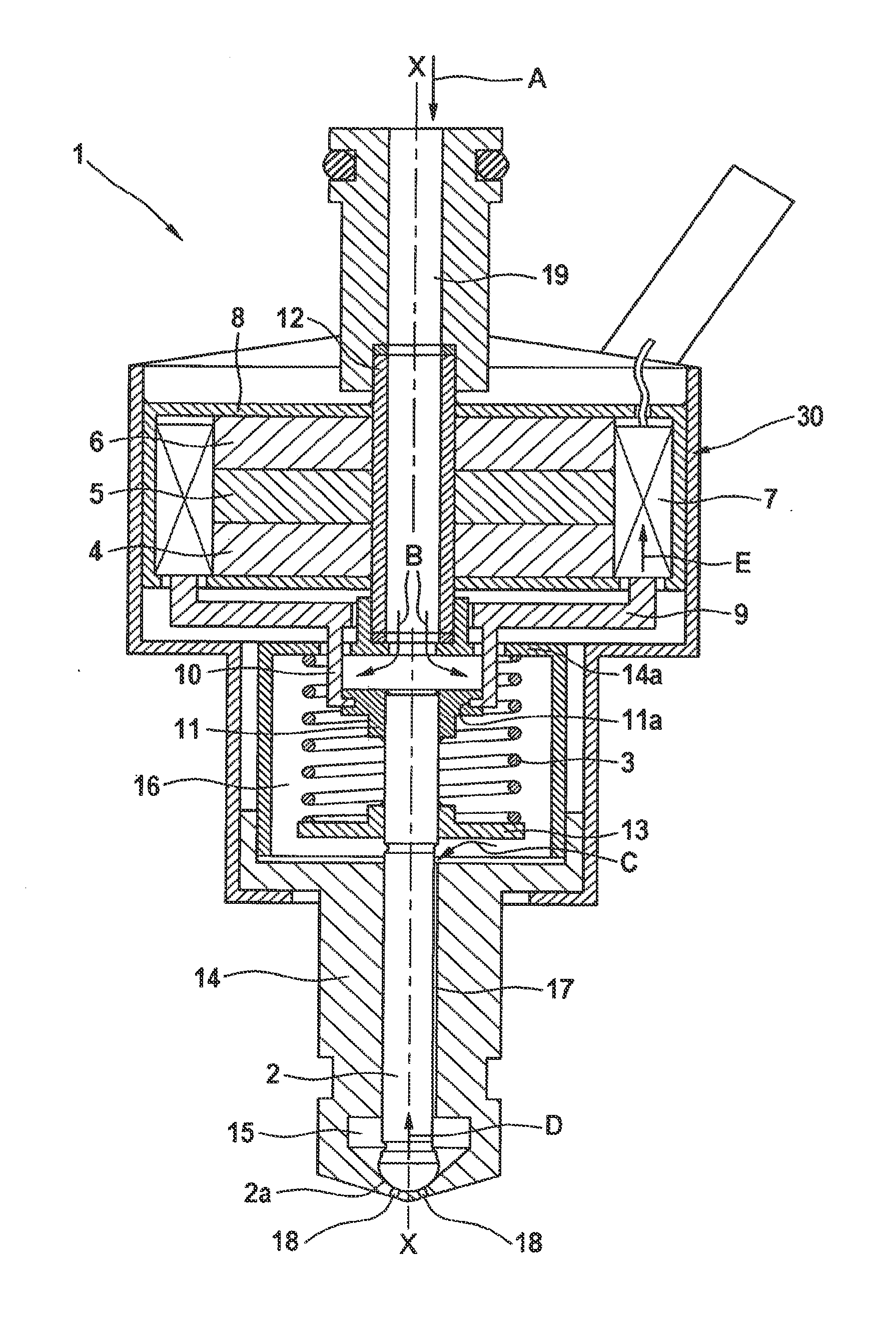
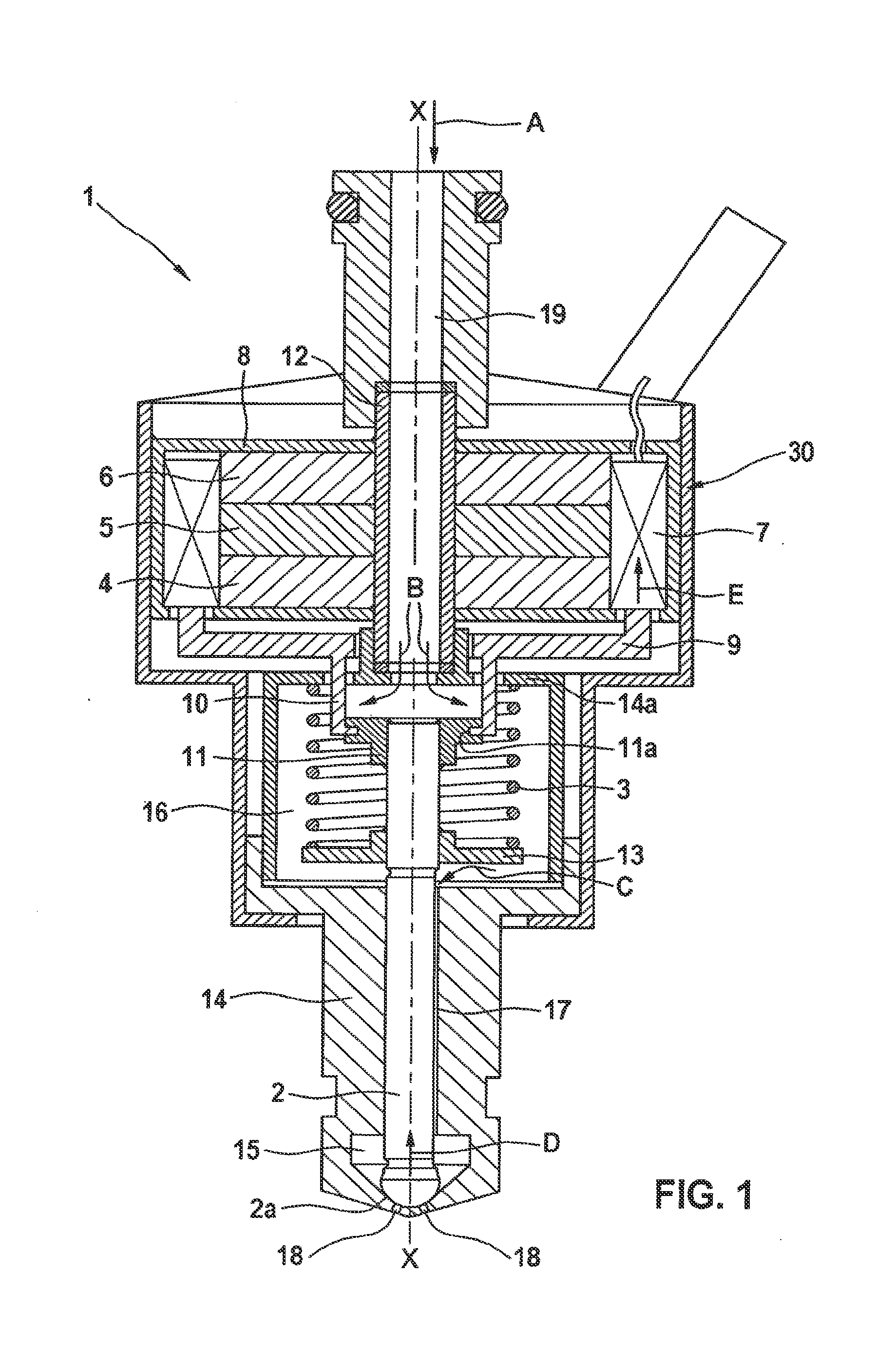
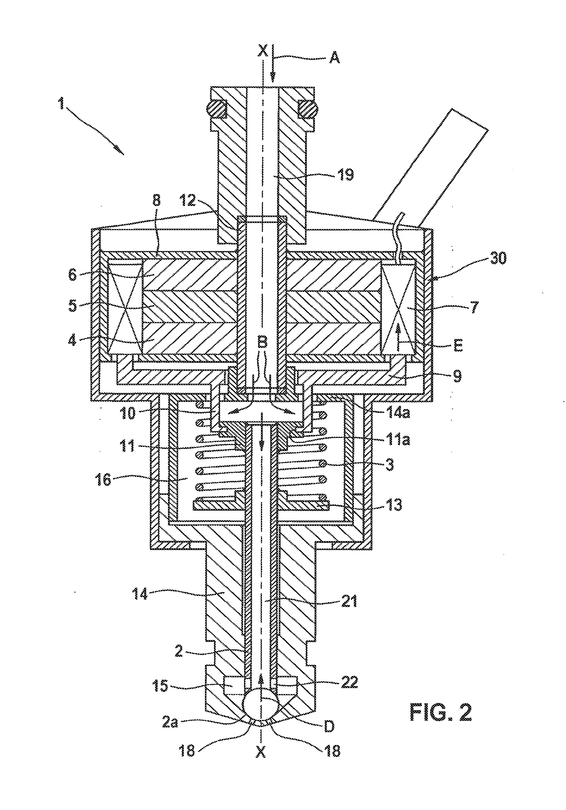
[0021]A device 1 for injecting fuel which is under high pressure is described in greater detail below with reference to FIG. 1.

[0022]As is apparent in FIG. 1, device 1 includes an electrodynamic actuator 30, a needle 2, and a fuel supply line 19. A fuel under high pressure is supplied to device 1 via fuel supply line 19. Electrodynamic actuator 30 includes a first permanent magnet 4, a second permanent magnet 6, a spacer disk 5, a movable coil 7, and a casing 8. Spacer disk 5 is made of a magnetically conductive material, and is situated between first permanent magnet 4 and second permanent magnet 6. Movably situated coil 7 is situated at the outer periphery of first and second permanent magnets 4, 6 and of spacer disk 5. Casing 8 is likewise made of a magnetically conductive material, and encloses coil 7 at the periphery as well as the two end faces of first permanent magnet 4 and second permanent magnet 6 in axial direction X-X. The two permanent magnets 4, 6 are situated in such ...


PUM


Abstract

A device for injecting fuel includes an electrodynamic drive having a movably situated coil, an inwardly opening needle which opens and closes injection holes on a valve seat, a connecting element which connects the needle to the movably situated coil, and a pressure chamber which is situated at the needle upstream from the valve seat and contains pressurized fuel.

Description

CROSS-REFERENCE TO RELATED APPLICATIONS[0001]The present application is a divisional application of U.S. patent application Ser. No. 13 / 138,121, filed Sep. 14, 2011, which is a national phase to International Application No. PCT / EP2009 / 065966, filed Nov. 27, 2009, and claims priority to German Patent Application No. 10 2009 000 185.9, filed Jan. 13, 2009, all of which are hereby incorporated by reference in their entireties.BACKGROUND OF THE INVENTION[0002]1. Field of the Invention[0003]The present invention relates to a device for injecting fuel, in particular a pressurized fuel being injected into a combustion chamber of an internal combustion engine.[0004]2. Description of Related Art[0005]Known devices for injecting fuel are used, for example, for injecting fuel in vehicle engines. Besides injection of diesel fuel, gasoline is recently also injected. Frequently, for the fuel injection fuel is provided from a storage (rail) and injected into a combustion chamber or an intake mani...

Claims


Application Information

Patent Timeline
Patent Type & Authority Applications(United States)
IPC IPC(8): F02M51/06
CPCF02M51/0689F02M51/0621F02M51/0696F02M61/10F02M2200/707H01F7/066
Inventor GRANER, JUERGENMAIER, MARTINHOHL, GUENTHER
Owner ROBERT BOSCH GMBH
Why Eureka
Try Eureka