Radar level gauge with switch for selecting transmitter or receiver mode

a technology of radar level gauge and switch, which is applied in the direction of using reradiation, radio wave reradiation/reflection, measurement devices, etc., can solve the problems of degrading the sensitivity of the system, limited directional couplers, and high cost, and achieve the effect of improving the sensitivity of pulsed radar level gauge systems at cost efficient rates

Active Publication Date: 2007-06-19
ROSEMOUNT TANK RADAR
View PDF7 Cites 29 Cited by
  • Summary
  • Abstract
  • Description
  • Claims
  • Application Information

AI Technical Summary

Benefits of technology

[0006]It is an object of the present invention to cost efficiently improve the sensitivity of pulsed radar level gauge systems.
[0008]According to this design, the directional coupler, that previously was arranged between the transmitter and the signal medium interface, has been replaced by a switch. By controlling the switch, the signal medium interface is connected only to the transmitter during the transmission of the pulse, and only to the receiver during reception of the reflected pulse. In this way, signal losses can be reduced significantly compared to prior solutions, where the signal medium interface at all times was connected to both the transmitter and the receiver. Typically, 10 dB improvements have been experienced, which for practical hardware solutions may correspond to 2–3 times longer maximum measuring distance for an antenna system, or maybe 20 meters longer maximum measuring distance for a transmission line system.
[0012]In order to obtain a sufficiently short dead zone, the switch should have a very short switching time, in the order of ns. Preferably, the switching time is shorter than 20 ns. Such a short switching time can only be realized by a switch without moving parts, comprising very small scale components, either discrete components or in the form of an integrated circuit, and this limited size of the switch makes it unable to handle powers greater than a few Watts. However, in a typical RLG system, the transmitted power is significantly less than one Watt, preferably less than 20 mW, and normally limited to a few mW, or even μW. Thus, the limited power capacity of the switch is not a problem.
[0013]In the inventive RLG, it is advantageous to provide for a small signal attenuation between the switch and the receiver, in order to provide higher signal input strength to the receiver for enhancing measuring capability. This RLG should preferably include no significant further attenuation / isolation between the transmitter and receiver than that introduced by the switch itself.
[0018]If a satisfactory switching time can be obtained, the switch can be adapted to realize pulse generation, by connecting the signal medium interface to a DC voltage for a period of time equal to the desired pulse width and then disconnecting it. Such operation of the switch will eliminate the need for a separate signal generator, thus simplifying the system.

Problems solved by technology

Directional coupling divides the available power between transmission line and receiving line, thus introducing significant attenuation of both transmitted and received signals, degrading the sensitivity of the system.
This is in particular a problem for systems using a DC pulse, since the choice of directional coupler is limited by the extreme bandwidth of such a pulse, which includes also large wavelengths.
However, such solutions are expensive, and their performance is typically temperature dependent, making them unsuitable for use in radar level gauges.

Method used


Image

  • Radar level gauge with switch for selecting transmitter or receiver mode
  • Radar level gauge with switch for selecting transmitter or receiver mode
  • Radar level gauge with switch for selecting transmitter or receiver mode

Examples


Embodiment Construction

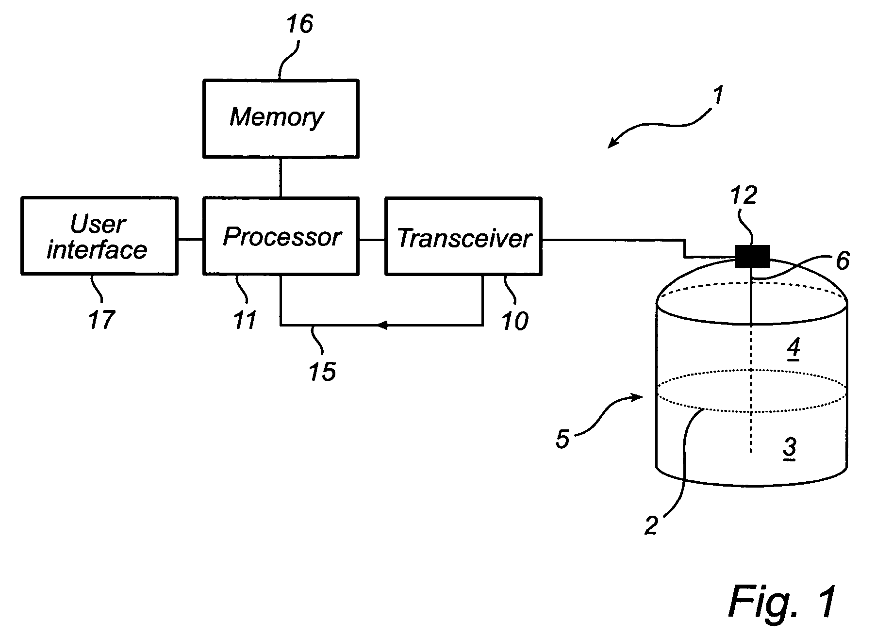
[0025]FIG. 1 shows schematically a radar level gauge (RLG) system 1 in which a method according to the invention may be advantageously used. The system 1 is arranged to perform measurements of a process variable in a tank, such as the level of an interface 2 between two (or more) materials 3, 4 in the tank 5. Typically, the first material 3 is a content stored in the tank, e.g. a liquid such as gasoline, while the second material 4 is air or some other atmosphere. In that case, the RLG will enable detection of the level of the surface of the content in the tank. Note that different tank contents have different impedance, and that the electromagnetic waves will not propagate through any material in the tank. Typically, therefore, only the level of a first liquid surface is measured, or a second liquid surface if the first liquid is sufficiently transparent.

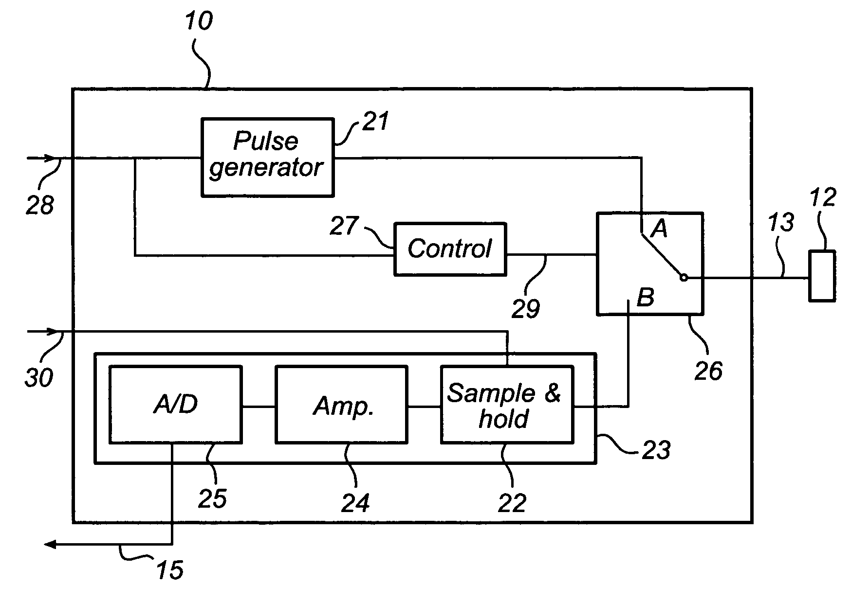
[0026]The system 1 comprises a transceiver 10, controlled by a processor 11 to transmit electromagnetic signals to a signal mediu...


PUM


Abstract

A radar level gauge (RLG), intended for measuring with a close-range low-power radar a distance to a content surface in a container relatively to a measuring position, which is located above the surface and fixed in relation to a lower boundary of said container. The RLG comprises a transmitter for transmitting an electromagnetic transmitter pulse, a signal medium interface connectable to means for directing said transmitter pulse towards said surface and for receiving a reception pulse reflected back from said surface, and a receiver for receiving said reception pulse. A switch connects said signal medium interface to said transmitter while said transmitter pulse is transmitted, and said signal medium interface to said receiver while said reflected pulse is received, the switch having a switching time short enough to enable short distance detection.According to this design, signal losses can be reduced significantly compared to prior solutions.

Description

FIELD OF THE INVENTION[0001]The present invention relates to a radar level gauge intended for measuring with a close-range low-power radar a distance to a surface of a content in a container relatively to a measuring position, which is located above the surface and fixed in relation to a lower boundary of said container.BACKGROUND[0002]Pulsed RLG (radar level gauging) is becoming a more widely spread method for industrial level gauging, due to its simple and cost effective microwave components. The pulse in a pulsed RLG can be modulated by a carrier frequency (typically 6 or 24 GHz), or be an unmodulated DC pulse. In the latter case, it is common to use some kind of transmission line (coaxial line, twin line, etc.), sometimes referred to as a probe, is usually used to guide the electro-magnetic signal through the material in the tank where it is reflected by one or more interface surfaces (such as air / liquid) between different parts of the tank content. In the former case a transmis...

Claims


Application Information

Patent Timeline
Patent Type & Authority Patents(United States)
IPC IPC(8): G01S13/08
CPCG01S7/034G01S13/10
Inventor ERIKSSON, MIKAEL
Owner ROSEMOUNT TANK RADAR
Why Eureka
Try Eureka