CAD integration through virtual persistent identifiers and design change recognition

a technology of persistent identifiers and cad, applied in the field of computer-aided design (cad) software integration solutions, can solve the problems of inability to integrate to the model, cost, and loss of design history in the process, and achieve the effect of reducing the cost of suppor

Active Publication Date: 2020-10-27
KIRKWOOD ROBERT
View PDF8 Cites 0 Cited by
  • Summary
  • Abstract
  • Description
  • Claims
  • Application Information

AI Technical Summary

Problems solved by technology

The suitable translator would function to re-assign entity identifiers each time a model is translated, but some design history would be lost in the process.
Other applications that depend on those identifiers to integrate to the model will fail to integrate.
Due to the number of potential combinations, this is expensive to support and limits software options.
The CAD / CAM industry has failed to resolve this incompatibility for the last forty five years.
Standards such as STEP (Standard for the Exchange of Product Model Data: ISO 10303) move the CAD data, but do not protect integration for multiple applications.

Method used


Image

  • CAD integration through virtual persistent identifiers and design change recognition
  • CAD integration through virtual persistent identifiers and design change recognition
  • CAD integration through virtual persistent identifiers and design change recognition

Examples


Embodiment Construction

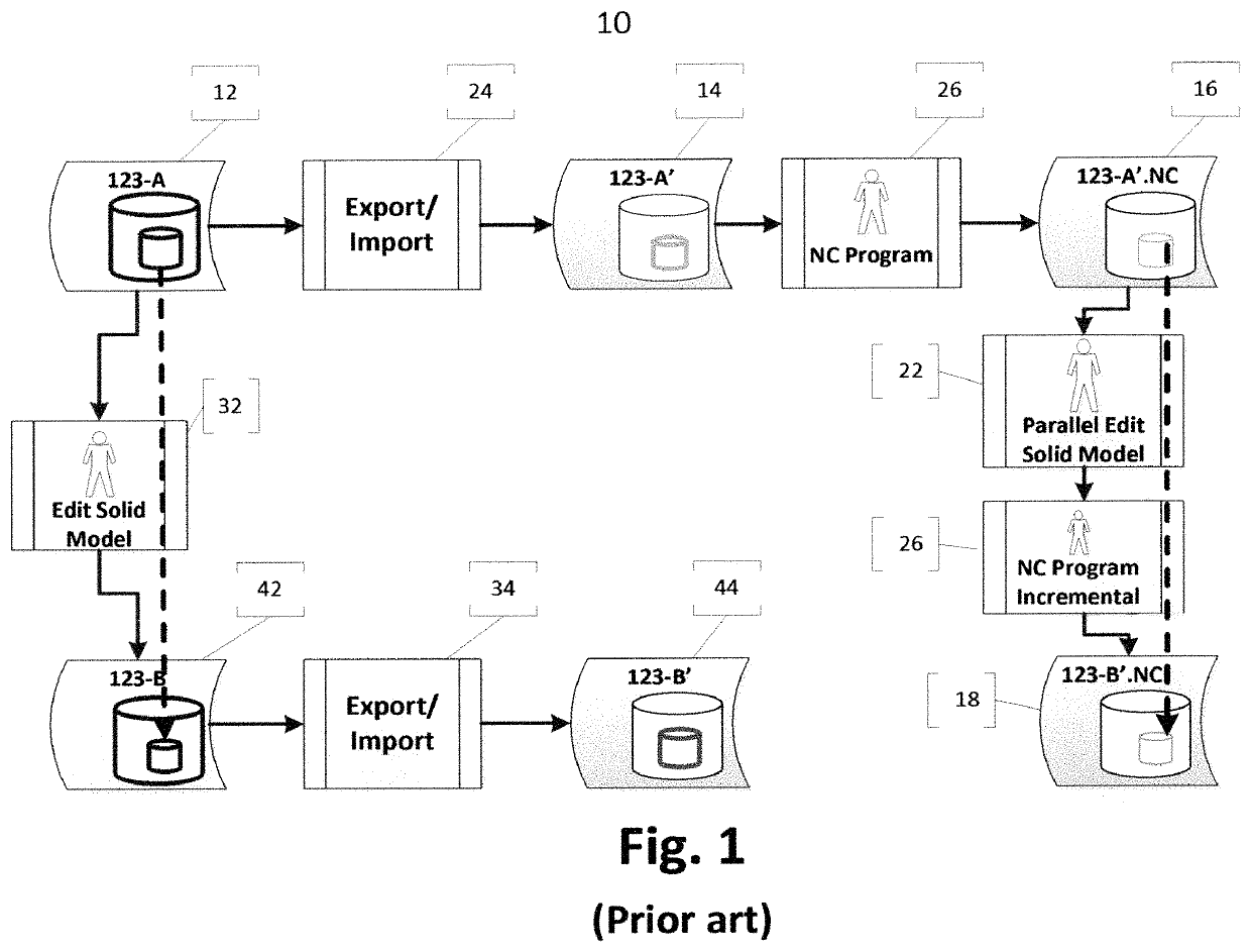
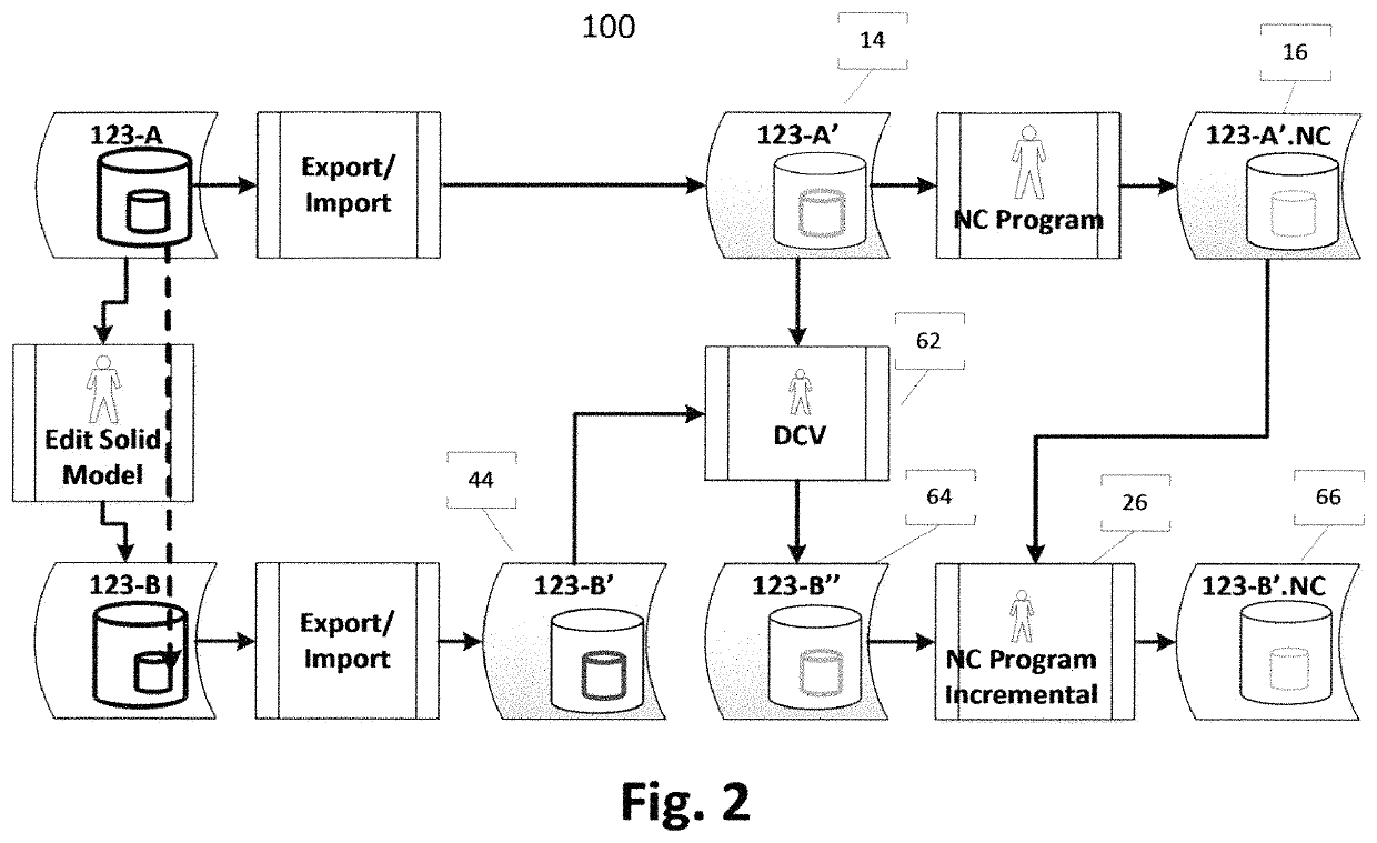
[0023]This invention is a process for enabling elements to provide a better alternative for integration with imported CAD models. The disclosed process is applied after engineering work has been performed based on an original model of a manufactured component, and wherein a subsequent model of the manufactured component has been imported by a client. At that point the resulting design changes can be determined through analysis of the model geometry and used to assign the same identifiers as used on the original model to each unchanged entity on the subsequent model. With stable identifiers on each new imported model, the native integration tools in the receiving CAD format will update any dependent engineering applications.

[0024]The disclosed process can be applied after the geometry of the manufactured component has been imported and used by a receiving application. The disclosed process can further be adapted for use with other engineering software applications, such as simulation...


PUM


Abstract

Disclosed is a method of integrating changes to a computer aided manufacturing software application file for a manufactured component comprising the steps of: obtaining a first computer aided design file for the manufactured component; displaying a first solid model of the manufactured component; obtaining a second computer aided design file for a revised version; displaying a second solid model of the revised version of the manufactured component; and matching at least one face on the second solid model to at least one face on the first solid model.

Description

FIELD OF THE INVENTION[0001]This invention relates to a computer-aided design (CAD) software Integration solution which provides for integration with imported CAD models.BACKGROUND OF THE INVENTION[0002]The current state of the art for CAD software is often unable to provide reliable, automatic, tight integration to CAD files imported from other CAD formats. FIG. 1 shows a typical engineering design workflow 10, as may be followed by a parts manufacturer. An engineer models a manufacturing component using a manufacturer CAD software program 22 to produce an original design CAD file 12 (123-A) for a client, for example. A manufacturer translator 24 is used to convert the original design CAD file 12 into a receiving format CAD file 14 (123-A′).[0003]The receiving format CAD file 14 is converted by using a manufacturer NC program 26 to produce an original design CAM file 16 (123-A′.NC) suitable for controlling one or more machining tools to fabricate the manufacturing component. The or...

Claims


Application Information

Patent Timeline
Patent Type & Authority Patents(United States)
IPC IPC(8): G05B19/4099G05B19/042
CPCG05B19/4099G05B2219/35134G05B2219/35085G05B19/0426G05B2219/35012Y02P90/02
Inventor KIRKWOOD, ROBERT
Owner KIRKWOOD ROBERT
Why Eureka
Try Eureka