Self-adaptive throwing device for stalks cutting and discharging in the longitudinal axial flow combine harvesters and its control method

a technology of throwing device and combine harvester, which is applied in the direction of mowers, agriculture tools and machines, etc., can solve the problems of not meeting the requirements of a combined harvester with a large feeding amount, the structure of the machine is more complex, and the discharging stalk is smaller, so as to increase the space occupied by the stalk, the effect of good adaptability and enhanced air flow speed

Active Publication Date: 2020-11-03
JIANGSU UNIV
View PDF49 Cites 1 Cited by
  • Summary
  • Abstract
  • Description
  • Claims
  • Application Information

AI Technical Summary

Benefits of technology

[0009]To solve the technical shortcomings of the above-mentioned stalks crushing and throwing device for discharged stalks, self-adaptive throwing device for stalks cutting and discharging in the longitudinal axial flow combine harvesters and its control system with an large feed quantity is provided to meet the requirements of cutting and throwing stalks at a feeding speed of 5 to 14 kg / s of the combine harvester. Moreover, the structure is compact, stalks after threshing and the remnant screened by the sieve surface can be effectively crushed and thrown. The device provided in the present invention has the advantages of large stalks discharging space, high crushing efficiency, evenly throwing and adaptive throwing width adjustment.
[0026](2) The self-adaptive throwing real-time control system performs pre-processing to the obtained real-time parameters, which mainly includes suppressing the interference, improving the signal-to-noise ratio and completing the missing data to eliminate the influence of random and uncertain factors on the subsequent data analysis.
[0029]In summary, the throwing width of the invention is self-adaptively adjustable according to the parameters such as the machine working speed, wind speed, wind direction, the position of the region having been cut and the position of the region waiting to be cut so as to realize the full width throwing of the stalks remnant. The shredded stems are uniformly scattered in the field, and it is also possible to avoid the scattering of the stem to the region waiting to be cut. The present invention has a good adaptability to the large feed amount of the combined harvester, and can meet the requirement for cutting and throwing stalks of longitudinal axis flow combine harvester in the feeding amount of 5 kg to 14 kg.
[0030]In addition, according to the invention, the arc stalk guiding plate and the flow separating bar are arranged at stalk discharging opening, and the stalks are separated into three stalk strips after the diversion function of the arc stalk guiding plate and the flow separating bar; after diversion, the transverse width of the stalk strip is approximately equal to the lateral width of the inlet of the stalk remnant shredding device, so that the crushing load of the stalks remnant shredding device is relatively uniform. The stalk containing space between the traditional stalks discharging and throwing device and the longitudinal axial flow cylinder is small, and in the case of large feeding amount, the amount of discharged stalks and broken spikes has also greatly increased, blockage is prone to occurring. While in the present invention, the shredder is lowered, increasing the stalks containing space so as to solve the problems such as unsmooth stalk discharging and blockage of the shredder caused by instantaneous excessive stalk discharging of longitudinal axial flow threshing cylinder.
[0031]By lowering the position of the shredder, the remnant screened by the upper sieved surface of the cleaning device can also be entered into the shredder, where the remnant and the stalks are simultaneously smashed and thrown; moreover, the air flow formed by the rotation of the blade enhanced the speed of the air flow on the tail of the upper sieve surface of the cleaning device, which is beneficial to the remnant discharge at the end of the upper sieve surface and improvement of the cleaning performance.

Problems solved by technology

However, the structure of the machine is more complex, the space for discharging stalks is smaller, and it cannot meet the requirement of the combined harvester with a large feeding amount in the aspect of shredding and throwing the discharged stalks.
However, when the stalks discharged from the threshing drum enter the grass chopper, the flow direction of the stalks is concentrated in one place and the stalks cannot be effectively spread, the local load on the chopper is too large, reducing the efficiency of crushing and throwing.
Moreover, the inclination of the guide plate cannot be adjusted adaptively.
However, since there is no stalks guide board, crushed stalks are note evenly distributed at the discharging opening of this kind of machine and diffusion is not achieved, the effect is not ideal.
In addition to the technical shortcomings described above, the above-mentioned patent cannot achieve the shredding and full-width dispel version of the mismatches discharged from the end surface of the shredded shaker of the combine harvesters.
The processing capacity and capacity of the traditional straw crushing and dispensing device used in the existing market do not match the harvest flow rate of the large feed, and the effect of the crushing and scattering of the stalk is not satisfactory.
The stalk containing space between the traditional stalks discharging and throwing device and the longitudinal axial flow cylinder is small, and in the case of large feeding amount, the amount of discharged stalks and broken spikes has also greatly increased, blockage is prone to occurring.

Method used


Image

  • Self-adaptive throwing device for stalks cutting and discharging in the longitudinal axial flow combine harvesters and its control method
  • Self-adaptive throwing device for stalks cutting and discharging in the longitudinal axial flow combine harvesters and its control method
  • Self-adaptive throwing device for stalks cutting and discharging in the longitudinal axial flow combine harvesters and its control method

Examples


Embodiment Construction

[0041]The present invention will now be described further with reference to the accompanying drawings and specific examples, but the scope of the present invention is not limited thereto.

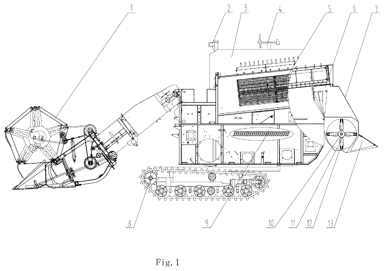
[0042]FIG. 1 shows the schematic left side view of the structure of the self-adaptive throwing device for stalks cutting and discharging in the longitudinal axial flow combine harvesters, the self-adaptive throwing device for stalks cutting and discharging in the longitudinal axial flow combine harvesters, comprising a longitudinal axial flow stalks discharging and guiding device 5, a stalks remnant shredding device 11, a wind direction and wind speed detection device 4, a reap region identification device 2, an operating speed sensor 8, a shredding revolution speed sensor 10, a width adjustable throwing device 13, and self-adaptive throwing real-time control system. The stalks remnant shredding device 11 is located behind and below the longitudinal axial flow stalks discharging and guiding device 5...


PUM


Abstract

A self-adaptive throwing device for stalks cutting and discharging in the longitudinal axial flow combine harvesters comprises a longitudinal axial flow stalk discharging and guiding device, a stalks remnant shredding device, a wind direction and wind speed detection device, a reaping region identification device, an operating speed sensor, a shredding revolution speed sensor, a width adjustable throwing device, a self-adaptive throwing real-time control system. The throwing width is self-adaptive based on the machine operating speed, wind speed, wind direction, the position of the region having been cut and the region waiting to be cut, so as to achieve the full width throwing of the stalks remnant. An arc stalk guiding plate and a flow separating bar are mounted in the longitudinal axial flow stalk guiding device to make the shredding load more even.

Description

CROSS REFERENCE TO RELATED APPLICATION[0001]The present application is a 371 U.S. National Stage of International Application No. PCT / CN2016 / 106705, filed Nov. 22, 2016, which claims the benefit of the earlier filing date of Chinese Patent Application No. 201610950735.X filed on Oct. 25, 2016, which are each incorporated herein by reference in their entirety.FIELD OF THE DISCLOSURE[0002]The invention belongs to the technical field of agricultural equipment and relates to a combine harvester, and in particular to a self-adaptive throwing device for stalks cutting and discharging in the longitudinal axial flow combine harvesters and its control method.BACKGROUND OF RELATED ART[0003]The present combine harvesters need to be equipped with straw crushing and throwing device during work, its function is discharging debris such as the stalks generated after the threshing and throwing it out of the machine after being crushed through the crushing and throwing device, and thus, evenly coveri...

Claims


Application Information

Patent Timeline
Patent Type & Authority Patents(United States)
IPC IPC(8): A01F12/40A01D41/06A01F12/60A01F12/44A01F12/22A01D41/127A01D41/12
CPCA01F12/40A01D41/1243A01F12/446A01D41/127A01F12/60A01F12/22A01D41/06
Inventor XU, LIZHANGLI, YANGLI, YAOMING
Owner JIANGSU UNIV
Why Eureka
Try Eureka