Electrical connector assembly and male connector
a technology of electrical connectors and connectors, applied in the direction of coupling devices, two-part coupling devices, securing/insulating coupling contact members, etc., can solve the problems of weak common ground performance difficult reduction of crosstalk of conventional electrical connectors, so as to improve the problem of the connection.
- Summary
- Abstract
- Description
- Claims
- Application Information
AI Technical Summary
Benefits of technology
Problems solved by technology
Method used
Image
Examples
first embodiment
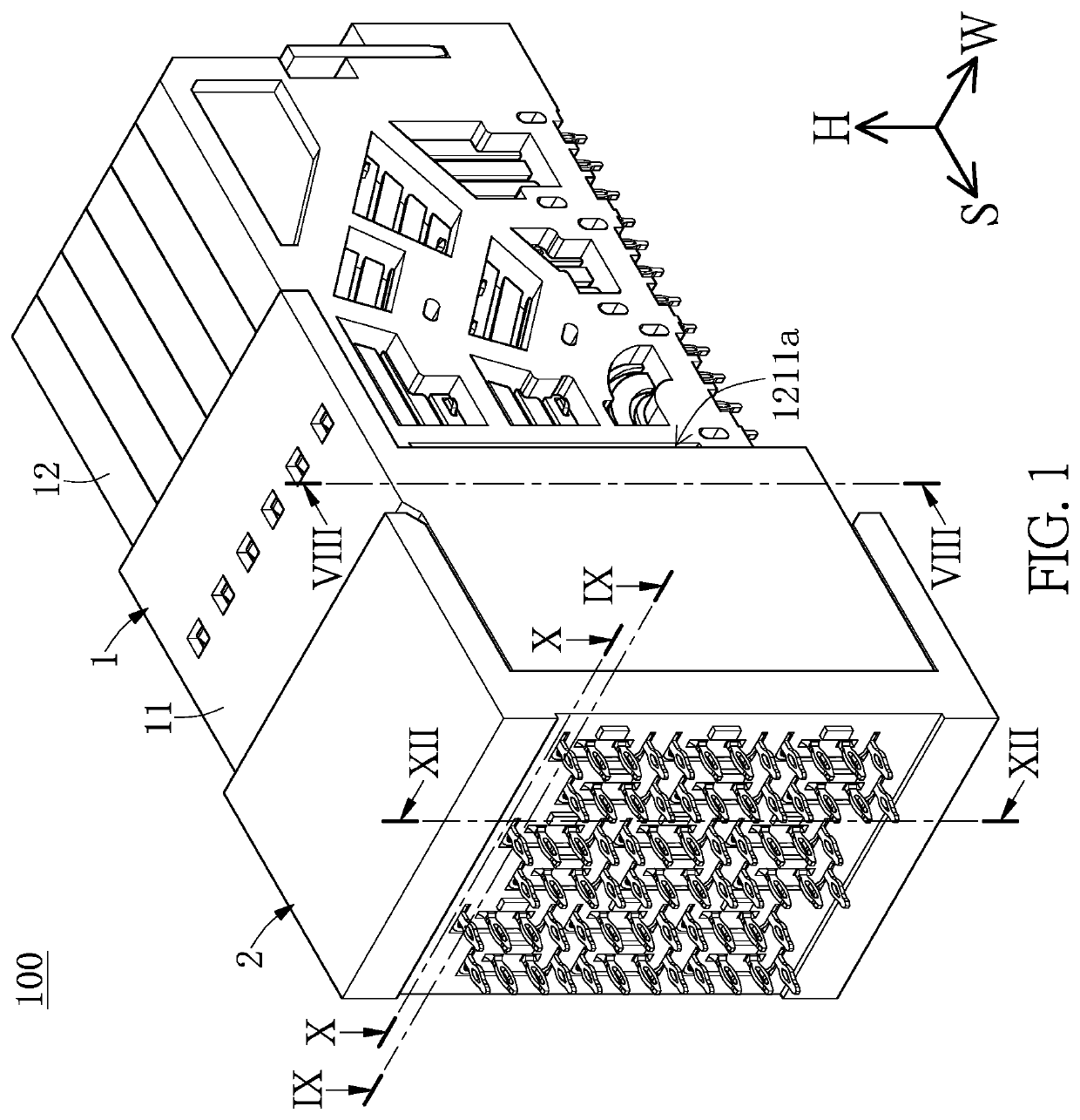
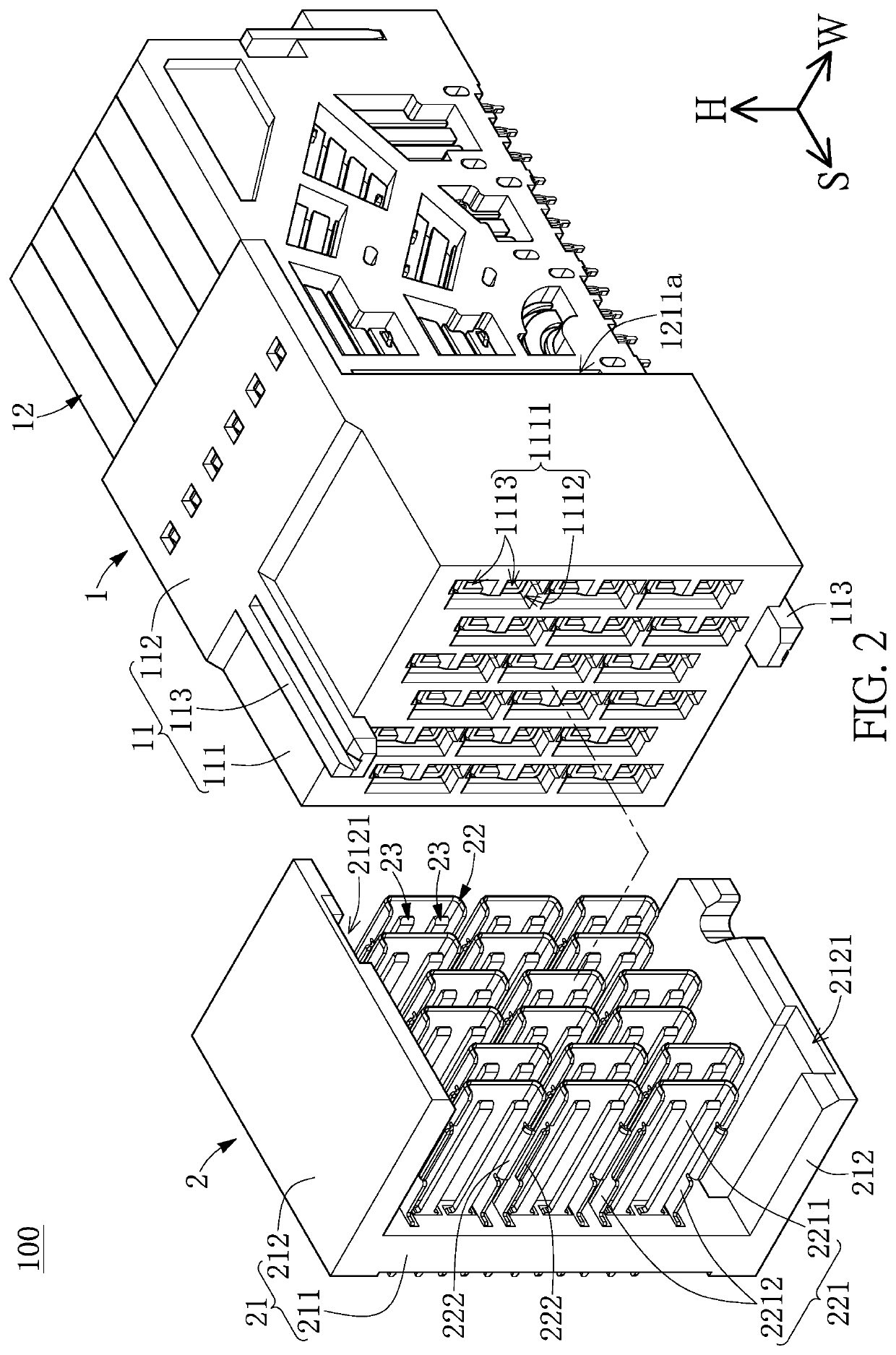
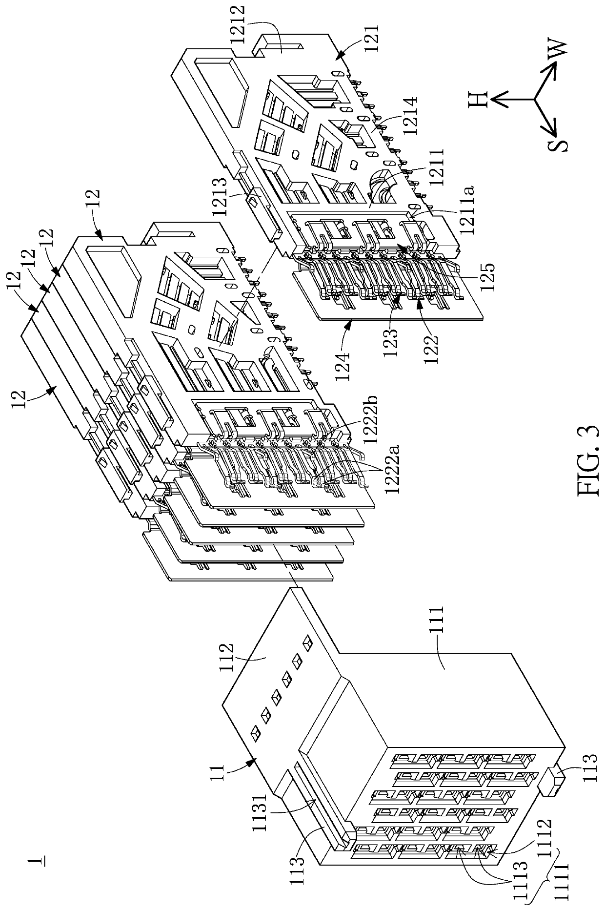
[0031]Referring to FIG. 1 to FIG. 12 and FIG. 17, a first embodiment of the present disclosure provides an electrical connector assembly 100 that can be applied to a server or a switchboard, but the present disclosure is not limited thereto. As shown in FIG. 1 and FIG. 2, the electrical connector assembly 100 includes a female connector 1 and a male connector 2 detachably inserted into the female connector 1 along an insertion direction S. In order to easily describe the present embodiment, the electrical connector assembly 100 further defines a width direction W and a height direction H both perpendicular to each other and perpendicular to the insertion direction S.
[0032]It should be noted that the female connector 1 and the male connector 2 in the present embodiment are in cooperation with each other, but the present disclosure is not limited thereto. In other embodiments of the present disclosure, the female connector 1 or the male connector 2 can be individually applied or can b...
second embodiment
[0074]Referring to FIG. 13 and FIG. 14, a second embodiment of the present disclosure is similar to the first embodiment of the present disclosure, so that the descriptions of the same components in the first and second embodiments of the present disclosure will be omitted for the sake of brevity, and the following description only discloses different features between the first and second embodiments (e.g., the female connector 1).
[0075]In the present embodiment, each of the grounding terminals 122 is not formed with the second contacting portion 1222b, and the front signal segment 1232 of each of the signal terminals 123 protrudes from the first contacting portions 1222a of any one of the grounding terminals 122. When the female connector 1 is inserted into the male connector 2, each of the first contacting portions 1222a is configured to be applied with a force so as to move along a first direction (e.g., the height direction H), each of the signal terminals 123 is configured to b...
third embodiment
[0077]Referring to FIG. 15, a third embodiment of the present disclosure is similar to the first embodiment of the present disclosure, so that the descriptions of the same components in the first and third embodiments of the present disclosure will be omitted for the sake of brevity, and the following description only discloses different features between the first and third embodiments (e.g., the male connector 2).
[0078]In the present embodiment, each of the rows of the shielding terminals 22 is integrally formed as a one-piece structure. In other words, in the two adjacent shielding terminals 22 arranged in the same row, two of the wing portions 222 respectively connected to the two adjacent side walls 2212 facing each other are integrally connected to each other, but the present disclosure is not limited thereto. For example, in other embodiments of the present disclosure, in each of the rows of the shielding terminals 22, only two of the shielding terminals 22 adjacent to each ot...
PUM
 Abstract
Description
Claims
Application Information
 - R&D
- Intellectual Property
- Life Sciences
- Materials
- Tech Scout
- Unparalleled Data Quality
- Higher Quality Content
- 60% Fewer Hallucinations
Browse by: Latest US Patents, China's latest patents, Technical Efficacy Thesaurus, Application Domain, Technology Topic, Popular Technical Reports.
© 2025 PatSnap. All rights reserved.Legal|Privacy policy|Modern Slavery Act Transparency Statement|Sitemap|About US| Contact US: help@patsnap.com


