Synchronous backlight device and operation method thereof

a backlight device and synchronous technology, applied in the field of display devices, can solve the problems of motion blur to the lcd panel, backlight flicker issue may arise to the backlight device, etc., and achieve the effect of improving the issue of backlight flicker

Active Publication Date: 2019-05-30
NOVATEK MICROELECTRONICS CORP
View PDF0 Cites 6 Cited by
  • Summary
  • Abstract
  • Description
  • Claims
  • Application Information

AI Technical Summary

Benefits of technology

The invention is a synchronous backlight device and operation method that addresses the problem of backlight flicker. By dividing each video frame period into two parts, the device can adjust the frequency of the PWM control signal to provide compensation light in the second period. This results in a more stable light output and reduces flicker. Overall, the device and method improve the quality of the backlighting.

Problems solved by technology

An issue of motion blur may occurs to the LCD panel using the asynchronous backlight.
For the LCD panel using the synchronous backlight, an issue of backlight flicker may arise to the backlight device of the related art because the period length of the vertical sync signal Vsync is not fixed.

Method used


Image

  • Synchronous backlight device and operation method thereof
  • Synchronous backlight device and operation method thereof
  • Synchronous backlight device and operation method thereof

Examples


Embodiment Construction

[0021]A term “couple” used in the full text of the disclosure (including the claims) refers to any direct and indirect connections. For instance, if a first device is described to be coupled to a second device, it is interpreted as that the first device is directly coupled to the second device, or the first device is indirectly coupled to the second device through other devices or connection means. Moreover, wherever possible, components / members / steps using the same referral numerals in the drawings and description refer to the same or like parts. Components / members / steps using the same referral numerals or using the same terms in different embodiments may cross-refer related descriptions.

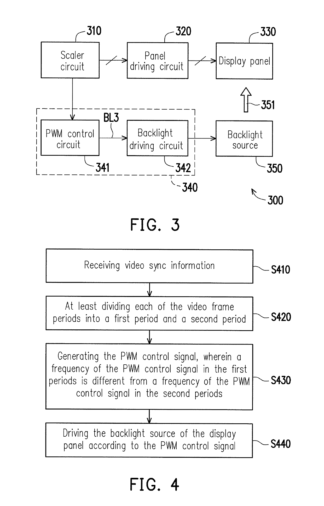
[0022]FIG. 3 is a schematic circuit block diagram illustrating a display device 300 according to an embodiment of the invention. The display device 300 includes a video processing circuit, which is, for example, a scaler circuit 310 and / or any other video signal processing circuit. The display devi...


PUM

PropertyMeasurementUnit
frequencyaaaaaaaaaa
lengthsaaaaaaaaaa
voltageaaaaaaaaaa

Abstract

A synchronous backlight device and an operation method thereof are provided. The synchronous backlight device includes a pulse width modulation (PWM) control circuit and a backlight driving circuit. The PWM control circuit receives the video sync information from a video processing circuit and generates a PWM control signal. Wherein, the video sync information defines a plurality of video frame periods, the PWM control circuit at least divides each of the video frame periods into a first period and a second period, the lengths of the first periods of the video frame periods are equal to one another. The frequency of the PWM control signal in the first periods is different from the frequency of the PWM control signal in the second periods. The backlight driving circuit drives the backlight source of a display panel in accordance with the PWM control signal.

Description

BACKGROUNDField of the Invention[0001]The invention relates to a display device and more particularly, to a synchronous backlight device and an operation method thereof.Description of Related Art[0002]FIG. 1 is a schematic waveform diagram of a backlight control signal BL1 when a backlight device of the related art controls / drives a backlight source in an asynchronous manner. In FIG. 1, the vertical axis represents the voltage, and the horizontal axis represents the time. In FIG. 1, Vsync represents a vertical sync signal, and DE represents a data enablement signal. A video processing circuit (not shown) may transmit the vertical sync signal Vsync and the data enablement signal DE to a panel driving circuit (not shown), so as to control the panel driving circuit to drive a liquid crystal display (LCD) panel (not shown). The vertical sync signal Vsync defines a plurality of video frame periods, for example, video frame periods F1, F2, F3 and F4 as illustrated in FIG. 1. As illustrate...

Claims


Application Information

Patent Timeline
Patent Type & Authority Applications(United States)
IPC IPC(8): G09G3/34H03K7/08G02F1/1335
CPCG09G3/3406H03K7/08G02F1/133602G09G2310/08G09G2310/0264G09G2320/0247G09G2320/064
Inventor WU, CHUNG-WENLIN, WEN-CHIWANG, SIH-TING
Owner NOVATEK MICROELECTRONICS CORP
Why Eureka
Try Eureka