Indoor illumination system

a technology of indoor illumination and cornice, which is applied in the direction of lighting support devices, instruments, lighting and heating apparatus, etc., can solve the problems of reducing the efficiency of projector lighting, reducing the efficiency of emitted light into directions where it is not needed, and the prior art side emitting sources are not ideal for projector lighting, etc., to achieve the effect of greatly reducing or eliminating problems such as glare, improving problems with conventional light sources, and reducing the illumination around corni

Inactive Publication Date: 2012-07-19
SHARP KK
View PDF10 Cites 6 Cited by
  • Summary
  • Abstract
  • Description
  • Claims
  • Application Information

AI Technical Summary

Benefits of technology

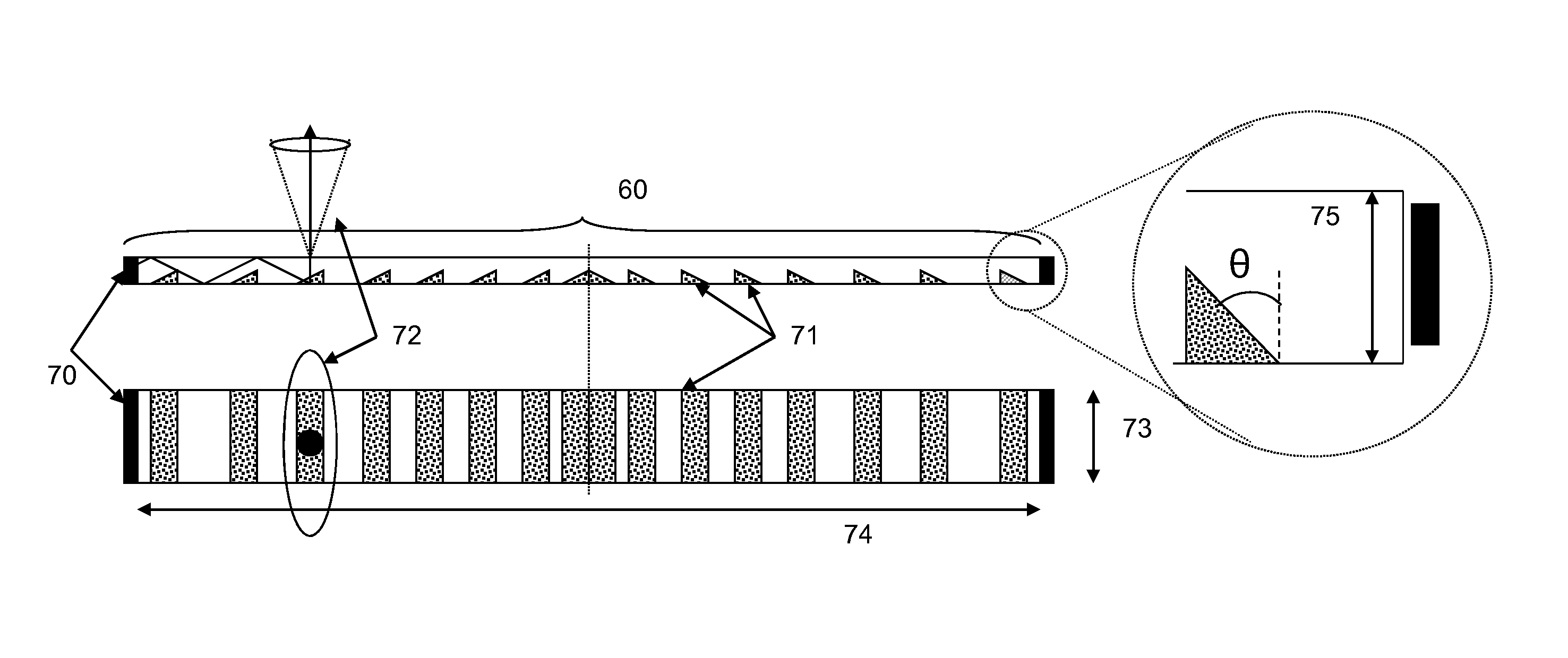
[0013]The present invention provides a lighting system which is able to improve issues with conventional light sources by introducing a method of providing light to a room from a cornice or equivalent location near the upper part of walls. Subsequently this area will be referred to as the cornice, but refers to the same location whether or not a cornice molding is present. The lighting system in accordance with the invention includes directional control such that light can be transmitted from some parts of the cornice but not all. The emission of light from the cornice may be achieved either directly from a light source positioned at that location, or by projecting light from another point in the room such that it reflects off the cornice.
[0014]Advantages of such a system are multiple; to achieve the same light levels in the room as from a single point source, the illuminance around a cornice can be much lower, hence the light source is more comfortable to look at and problems with glare are greatly reduced or eliminated. A light source from multiple locations will also greatly reduce shadowing.
[0015]By providing directional control, light levels in various parts of a room can be adjusted to give optimum brightness in each, and the efficiency of the lighting system will be increased through the reduction of wasted light. Further advantages include the fact that light sources designed to project light towards the cornice can also be retrofitted in many locations since ceiling lights are often fitted in the centre of a room, and could easily be replaced with a projection light source.

Problems solved by technology

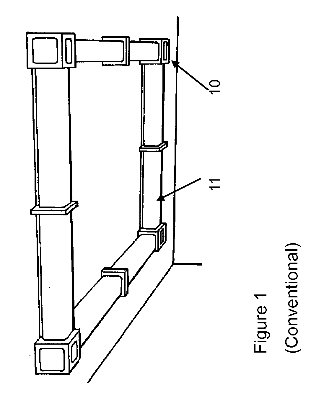
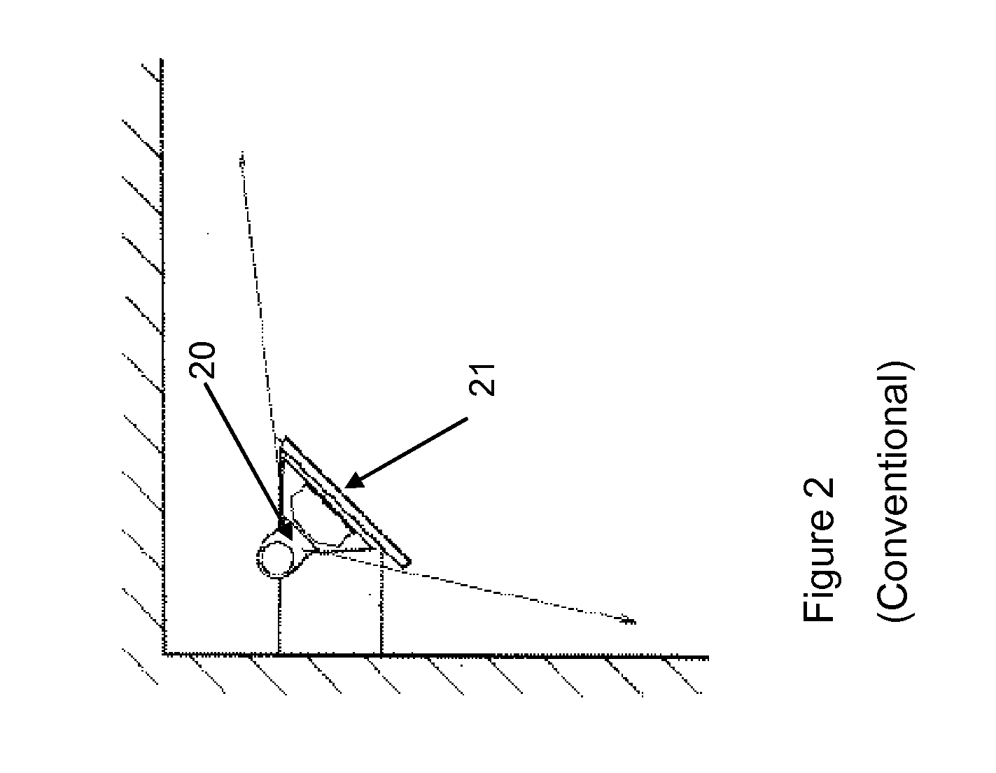
There are problems with existing lighting systems, as described in the background section, which include issues with glare from small point or narrow line sources; strong shadowing from the same; lack of control over lighting directionality, and reduced efficiency caused by emitting light into directions where it is not needed.
Side emitting sources in the prior art are not ideal for projection lighting because they are designed to emit into a relatively wide angular range, as is necessary for in-coupling and subsequent extraction in lightguides.

Method used


Image

  • Indoor illumination system
  • Indoor illumination system
  • Indoor illumination system

Examples


third embodiment

[0126]In a third embodiment in accordance with the invention, illustrated in FIG. 8, the light source may be as described above, but located on the ceiling 80, away from the walls (e.g., a predetermined distance from the walls), in order to direct light towards the middle of the room or interior space. This may be particularly desirable in, but is not limited to, larger areas where a cornice mounted light source 60 may not provide sufficient illumination further away from the walls.

fourth embodiment

[0127]A fourth embodiment in accordance with the present invention describes a combination of the previous embodiments, with light guide light sources located both on the cornice 60 and the ceiling 80 for optimum room illumination. This embodiment is illustrated in FIG. 9.

fifth embodiment

[0128]In a fifth embodiment in accordance with the present invention, illustrated in FIG. 10, the light source 100 is much smaller than the illumination area, and is located away from the cornice, for example in the centre of the ceiling. In this case the light source is in-coupled to an optic 101 which projects illumination 103 towards the cornice, where the light is then redirected into the room via reflection or scattering. For example, the light source maybe configured to project light from a light exit surface toward a target area.

[0129]The light source may include, but is not limited to, one or more LEDs coupled to a side-emitting optic. The optic material should be a transparent material such as glass or PMMA. An example optic geometry is shown in FIG. 11. In this example the optic first collimates the LED output, positioned at 110 (e.g., a light receiving surface), through a combination of refraction and total internal reflection on collimating surface 111 (which is arranged...


PUM


Abstract

A lighting system for an indoor room or space is designed to provide a diffuse, glare free source that illuminates the room from the cornice, or a similar location around the join between the walls and ceiling. This may be achieved via a direct source of illumination at the cornice location, or by projecting illumination from a remote source. The lighting system is further designed to allow for illumination of certain areas of the cornice, and hence the room, whilst leaving other parts dark. There are multiple advantages of an adaptable system such as this, but in particular the lighting conditions can be adjusted for optimum lighting levels, for example dimming selected areas when viewing a television.

Description

TECHNICAL FIELD[0001]The present invention relates to a lighting system, and, more particularly, to a lighting system capable of providing diffuse, glare free lighting in an indoor environment. The lighting system has the further capability of limiting illumination to some areas of this indoor space as selected by a user.BACKGROUND ART[0002]Artificial light sources, from the candle to the incandescent bulb to LEDs, tend to be highly localized point sources. There are a few exceptions—fluorescent tube lighting being an obvious example—but even in these cases the light source is confined to a relatively small volume. These light sources can be highly directional, such as spot lighting, and designed to emit into a narrow cone angle. Alternatively, as is the case for traditional incandescent filament lights or cold cathode fluorescent lights (CFLs), the emission is much closer to isotropic, with very little directional or angular control. In either case, emission from a relatively small...

Claims


Application Information

Patent Timeline
Patent Type & Authority Applications(United States)
IPC IPC(8): F21V7/22F21S8/04F21V7/10F21V11/00F21V21/00F21S6/00
CPCF21S2/00F21S8/037F21S10/06F21V5/04F21V5/046G02B6/0038F21V7/0091F21V13/04F21V17/02F21Y2101/02G02B6/0018F21V7/0008F21Y2115/10
Inventor MITCHELL, SARAH ANNEMONTGOMERY, DAVID JAMES
Owner SHARP KK
Why Eureka
Try Eureka