
Base station and method of controlling transmission/reception power

a technology of transmission/reception power and base station, which is applied in power management, electrical equipment, network topologies, etc., can solve the problems of increasing circuit scale, shortening the transfer time of notification signals, and increasing costs, so as to reduce the amount of information of notification signals that are transferred using a few control lines, shorten the time for power change processing, and increase the number of antennas

Active Publication Date: 2020-11-03
NIPPON TELEGRAPH & TELEPHONE CORP
View PDF8 Cites 0 Cited by
  • Summary
  • Abstract
  • Description
  • Claims
  • Application Information

AI Technical Summary

Benefits of technology

This patent is about a way to control the power of signals transmitted through multiple antennas. By setting a common power change amount for each target terminal and antenna, and adding up the individual power change amount for each target terminal, a power control unit can be used to manage the power of the signal transfer. This reduces the amount of information required to be transferred through a few control lines, which can make the power changing process faster and allow for high-speed signaling.

Problems solved by technology

However, because the n control lines are necessary, a problem of increasing a circuit scale and the cost occurs.
For example, there is a need to perform control to the precision of milliseconds or less to perform transmission power control on a per-wireless packet basis, and a problem of shortening the transfer time of the notification signal occurs.

Method used


Image

  • Base station and method of controlling transmission/reception power
  • Base station and method of controlling transmission/reception power
  • Base station and method of controlling transmission/reception power

Examples


Embodiment Construction

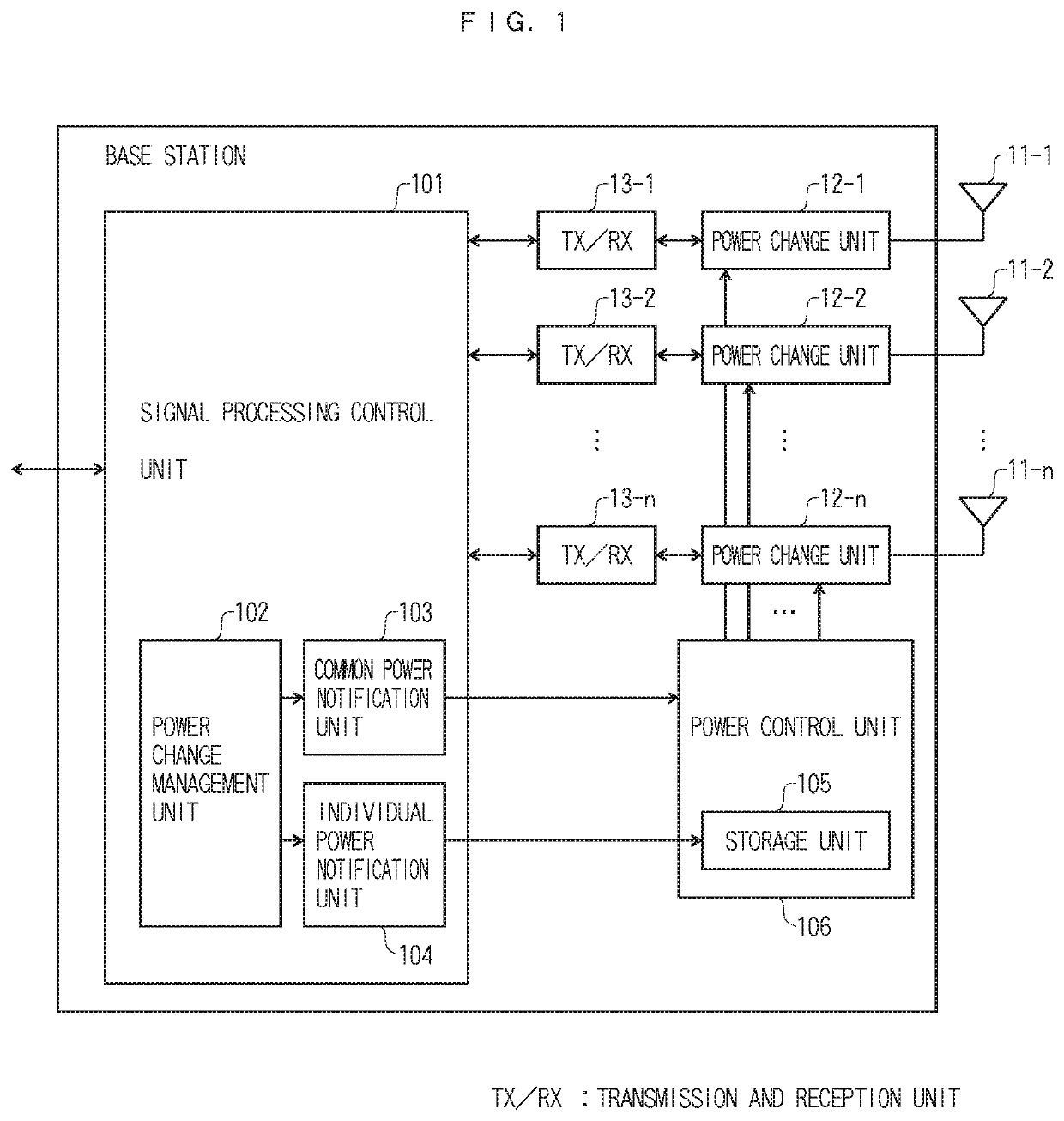
[0037]FIG. 1 illustrates an example of a configuration of a base station according to the present invention.

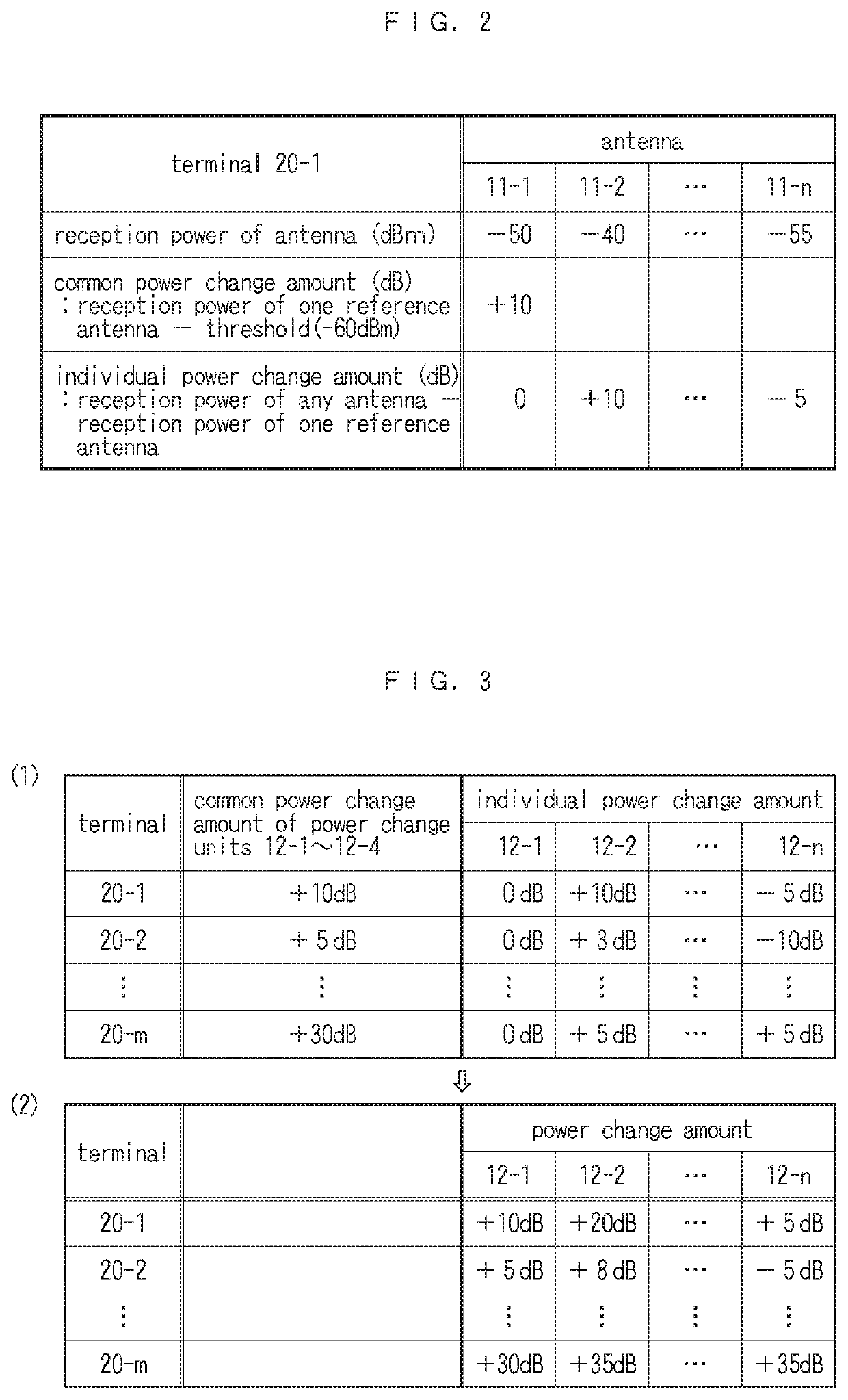
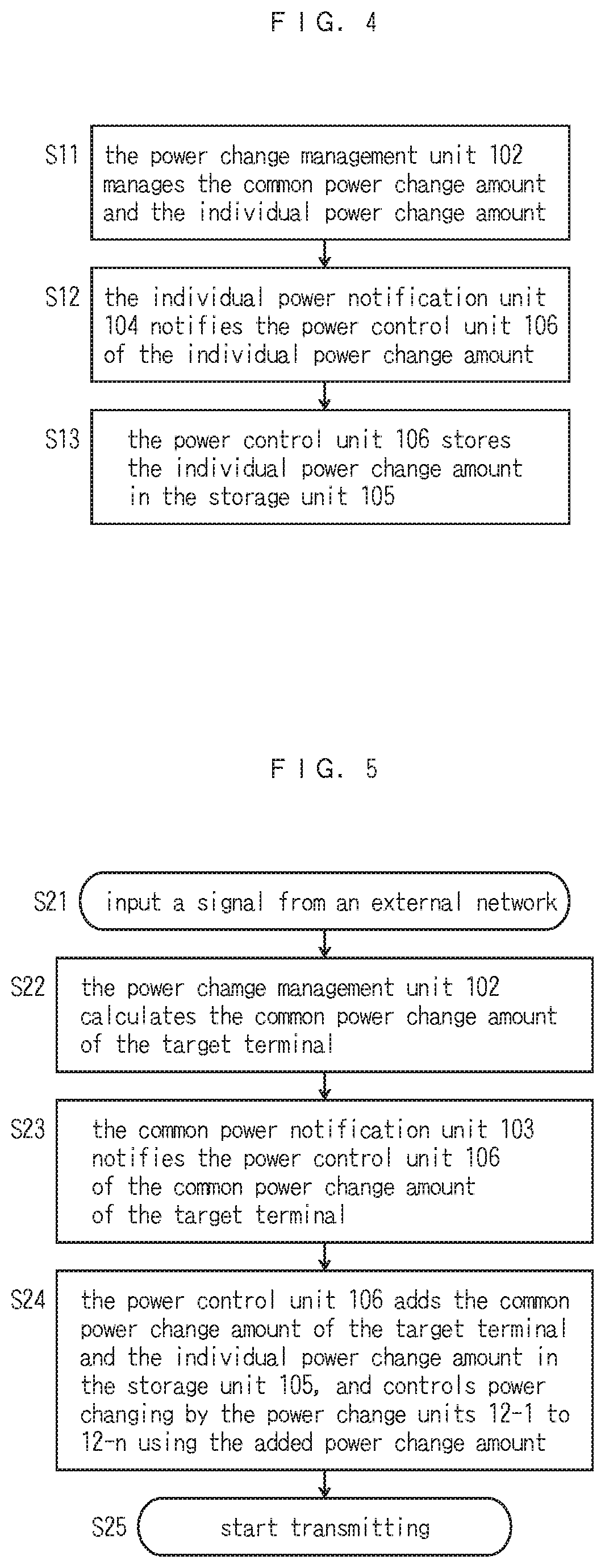
[0038]In FIG. 1, the base station includes n (n is an integer of two or more) antennas, antennas 11-1 to 11-n. Power change units 12-1 to 12-n change transmission powers and reception powers of signals that are transmitted or received in the antennas, respectively. Transmission and reception units 13-1 to 13-n perform transmission processing and reception processing of signals that are transmitted or received in the antennas, respectively. A signal processing control unit 101 performs conversion processing of a signal that is input and output into and from a network that is connected to the base station and a signal that is transmitted or received in each antenna. For management, a power change management unit 102 divides an amount of power change, which is set to be in the power change units 12-1 to 12-n, into a common power change amount, which is for every target terminal t...


PUM


Abstract

Provided are n antennas and n power change units; a power control unit; a power change management unit managing a common power change amount and an individual power change amount; a common power notification unit notifying the power control unit of the common power change amount in accordance with a target terminal; an individual power notification unit notifying the power control unit in advance of the individual power change amount in accordance with the each terminal at a prescribed timing, in which the power control unit stores the individual power change amount in a storage unit, and performs control of power changing by adding up the common power change amount in accordance with the target terminal, which is notified from the common power notification unit, and the individual power change amount.

Description

CROSS REFERENCE TO RELATED APPLICATIONS[0001]This application is a U.S. National Stage Application claiming the benefit of prior filed International Application No. PCT / JP2018 / 002296 filed on Jan. 25, 2018, in which the International Application claims priority from Japanese Patent Application No. 2017-013221, filed on Jan. 27, 2017. The entire disclosures of the above applications are incorporated herein by reference.TECHNICAL FIELD[0002]The present invention relates to a base station that performs wireless communication by sharing the same frequency channel with one or more terminals using multiple antennas and that controls a transmission power or a reception power of each antenna and thus improves throughput, and a method of controlling the transmission power or the reception power.BACKGROUND ART[0003]In recent years, with the spread of a high-performance portable wireless terminal, such as a smartphone, wireless LANs in compliance with the IEEE 802.11 standard have come into wi...

Claims


Application Information

Patent Timeline
Patent Type & Authority Patents(United States)
IPC IPC(8): H04W52/14H04W52/24H04W52/30H04W88/08H04W16/28H04W52/36H04W84/12
CPCH04W52/245H04W16/28H04W52/143H04W88/08H04W52/36H04W84/12H04W52/52H04W52/10H04B7/0413H03G3/3036H04B7/0452H04W52/42H04B7/0426
Inventor MURAKAMI, TOMOKIISHIHARA, KOICHITAKATORI, YASUSHIABEYSEKERA, HIRANTHAAKIMOTO, MAMORU
Owner NIPPON TELEGRAPH & TELEPHONE CORP
Learn More