Method and an apparatus for encoding a signal transporting data for reconstructing a sparse matrix

a sparse matrix and signal transport technology, applied in image analysis, color signal processing circuits, complex mathematical operations, etc., can solve the problems of slow and inefficient operation using standard dense matrix structures and algorithms, large sparse matrix manipulation is infeasible, and the access to individual elements becomes more complex

Inactive Publication Date: 2018-06-14
INTERDIGITAL VC HLDG INC
View PDF1 Cites 0 Cited by
  • Summary
  • Abstract
  • Description
  • Claims
  • Application Information

AI Technical Summary

Benefits of technology

[0044]It is thus, more convenient to arrange the parameter representative of colour data which are changing over time, e.g. for every image acquired by the optical device, in the same order in which the geometry data are encoded.

Problems solved by technology

Operations using standard dense-matrix structures and algorithms are slow and inefficient when applied to large sparse matrices as processing and memory are wasted on the null elements.
Some very large sparse matrices are infeasible to manipulate using standard dense-matrix algorithms.
The trade-off is that accessing the individual elements becomes more complex and additional structures are needed to be able to recover the original matrix unambiguously.
However, the methods for storing and transmitting sparse matrices are not appropriate to store and transmit matrices having more than two dimensions.

Method used


Image

  • Method and an apparatus for encoding a signal transporting data for reconstructing a sparse matrix
  • Method and an apparatus for encoding a signal transporting data for reconstructing a sparse matrix
  • Method and an apparatus for encoding a signal transporting data for reconstructing a sparse matrix

Examples


first embodiment

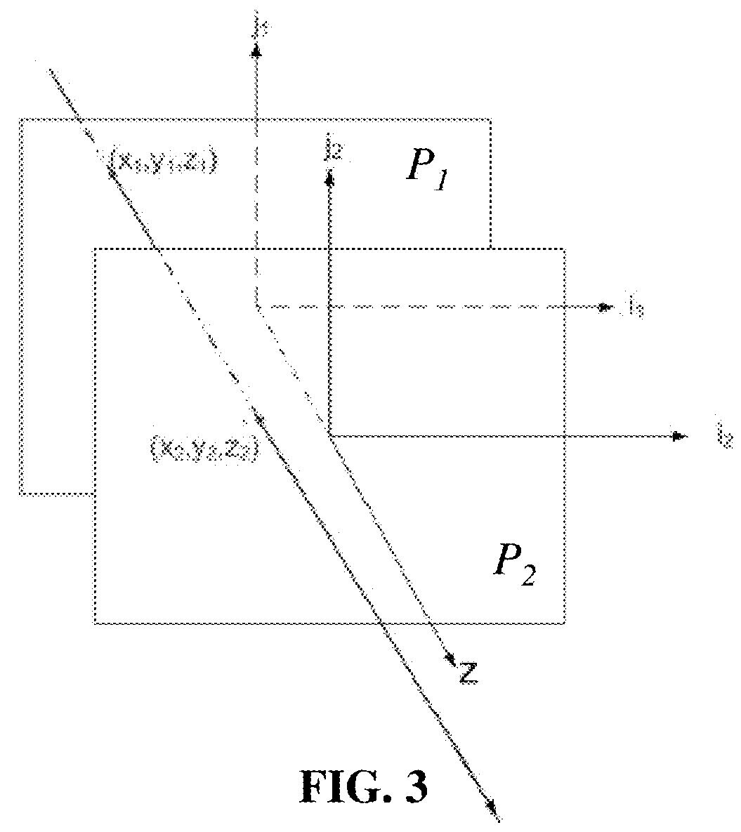
[0118]In a first embodiment, FIG. 3 illustrates a ray of light passing through two reference planes P1 and P2 used for parameterization positioned parallel to one another and located at known depths z1 and z2 respectively. The z direction, or depth direction, corresponds to the direction of the optical axis of the optical device used to obtain the light field data.

[0119]The ray of light intersects the first reference plane P1 at depth z1 at intersection point (x1, y1) and intersects the second reference plane P2 at depth z2 at intersection point (x2, y2). In this way, given z1 and z2, the ray of light can be identified by four coordinates (x1, y1, x2, y2). The light-field can thus be parameterized by a pair of reference planes for parameterization P1, P2 also referred herein as parameterization planes, with each ray of light being represented as a point (x1, y1, x2, y2,)∈R4 in 4D ray space.

second embodiment

[0120]In a second embodiment represented on FIG. 4, the ray of light is parameterized by means a point of intersection between a reference plane P3 located at known depths z3 and the ray of light.

[0121]The ray of light intersects the reference plane P3 at depth z3 at intersection point (x3, y3). A normalized vector v, which provides the direction of the ray of light in space has the following coordinates: (vx, vy, √{square root over (1−(vx2+vy2))}), since vz=√{square root over (1−(vx2+vy2))} vz is assumed to be positive and it can be recalculated knowing vx and vy, the vector can be described only by its two first coordinates (vx, vy).

[0122]According to this second embodiment, the ray of light may be identified by four coordinates (x3, y3, vx, vy). The light-field can thus be parameterized by a reference plane for parameterization P3 also referred herein as parameterization plane, with each ray of light being represented as a point (x3, y3, vx, vy,)∈R4 in 4D ray space.

[0123]The inve...


PUM


Abstract

The disclosure relates to method for storing and transmitting sparse matrices in compact way. When storing and manipulating sparse matrices on a device, it is beneficial and often necessary to use specialized algorithms and data structures that take advantage of the sparse structure of the matrix. The trade-off is that accessing the individual elements becomes more complex and additional structures are needed to be able to recover the original matrix unambiguously. The method according to an embodiment includes storing indexes enabling the position in the matrix of non-null elements to be determined in an ordered way, so as to limit the amount of information to be encoded, and thus reduce the amount of data to be transmitted. The encoded information is sufficient for enabling the reconstruction of the matrix on a receiver.

Description

RELATED EUROPEAN APPLICATION[0001]This application claims priority from European Patent Application No. 16306664.0, entitled “A METHOD AND AN APPARATUS FOR ENCODING A SIGNAL TRANSPORTING DATA FOR RECONSTRUCTING A SPARSE MATRIX”, filed on Dec. 12, 2016, the contents of which are hereby incorporated by reference in its entirety.TECHNICAL FIELD[0002]The present invention relates to method for storing and transmitting sparse matrices in compact way. More particularly the invention concerns the storing and transmitting of sparse matrices containing data representative of light-field contents in a compact way.BACKGROUND[0003]A sparse matrix is a matrix in which most of the elements are null, i.e. their value is equal to zero. The number of null elements divided by the total number of elements is called the sparsity of the matrix.[0004]When storing and manipulating sparse matrices on a device, it is beneficial and often necessary to use specialized algorithms and data structures that take ...

Claims


Application Information

Patent Timeline
Patent Type & Authority Applications(United States)
IPC IPC(8): G06F17/16H04N19/60H04N19/85
CPCG06F17/16H04N19/60H04N19/85H04N19/42H04N19/126H04N19/182G06T7/557H04N9/67H04N23/957H04N23/80H04N23/57
Inventor KERBIRIOU, PAULDAMGHANIAN, MITRABURELLER, OLIVIER
Owner INTERDIGITAL VC HLDG INC
Why Eureka
Try Eureka