Communication Method
a communication method and communication technology, applied in the field of communication methods, can solve problems such as overhead increase, and achieve the effect of improving throughpu
- Summary
- Abstract
- Description
- Claims
- Application Information
AI Technical Summary
Benefits of technology
Problems solved by technology
Method used
Image
Examples
first embodiment
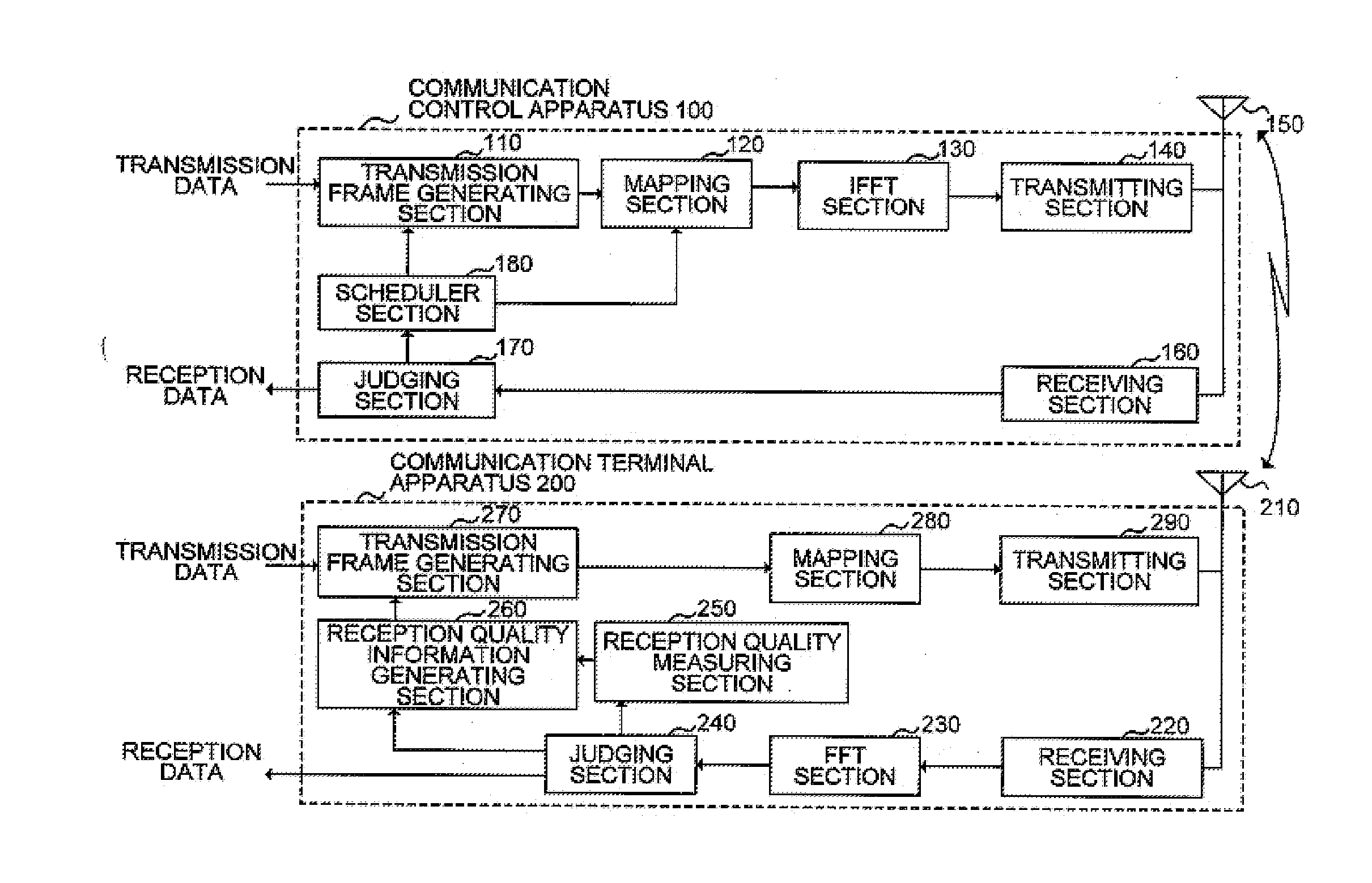
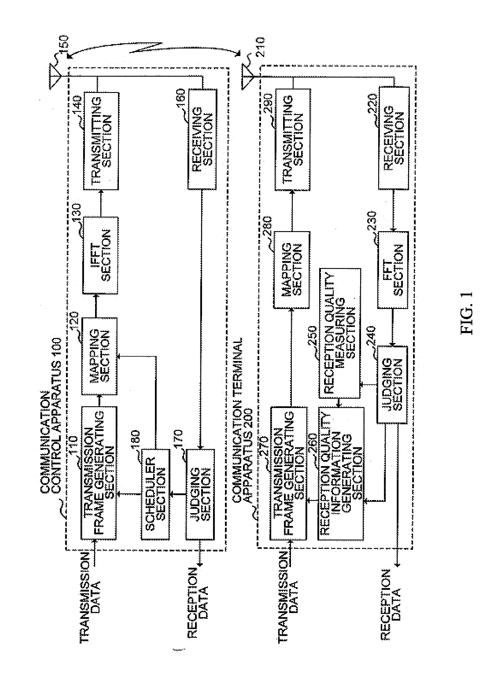
[0196]FIG. 1 is a block diagram showing a configuration example of a wireless communication system of the first embodiment according to the invention. In the following descriptions of each embodiment, the case will be described where CINR (Carrier-to-Interference plus Noise power Ratio) is used as reception quality, but other indexes are applicable as the reception quality. For example, indexes indicating the reception quality associated with received signal power and / or carrier power may be used such as RSSI (Receive Signal Strength Indication), SNR (Signal to Noise power Ration), SIR (Signal to Interference power Ratio), SINR (Signal to Interference plus Noise power Ration), CNR (Carrier to Noise power Ratio), CIR (Carrier to Interference power Ratio) and the like. Alternately, indexes indicating the reception quality associated with success or failure of reception may be used such as BER (Bit Error Rate), PER (Packet Error Rate), BLER (Block Error Rate) and the like. Further, in ...
second embodiment
[0234]The second embodiment describes an aspect that the communication control apparatus notifies the communication terminal apparatus of the last reception quality information. An OFDMA system of this embodiment uses the same configuration as in FIG. 1. Respects differing from the first embodiment will be focused below to explain. The components assigned the same reference numerals and names as those in FIG. 1 have the same functions.
[0235]In the communication control apparatus 100, the transmission frame generating section 110 generates a transmission frame from the transmission data according to the scheduling control information notified from the scheduler section 180. At this point, the section 110 performs channel coding according to the MCS information notified from the scheduler section 180. Further, in addition to the control data to notify the communication terminal apparatus 200 of the MCS information, the section 110 generates the control data to notify the communication...
third embodiment
[0263]The third embodiment describes an aspect where the communication control apparatus selects an allocation change candidate channel, and notifies the communication terminal apparatus of the reception quality information in the allocation change candidate channel.
[0264]FIG. 15 is a block diagram showing a configuration example of an OFDMA system of the third embodiment. The OFDMA system as shown in FIG. 15 is comprised of a communication control apparatus 300 and communication terminal apparatus 200, and has the components of FIG. 1 and an allocation change candidate channel selecting section 310 added to the communication control apparatus 300. Hereinafter, portions differing from FIG. 1 will be focused below to explain. The components assigned the same reference numerals and names as those in FIG. 1 have the same functions, and descriptions thereof are omitted.
[0265]The scheduler section 180 performs the operation of the data flow as shown in FIG. 11, and notifies the allocatio...
PUM
 Abstract
Description
Claims
Application Information
 - R&D
- Intellectual Property
- Life Sciences
- Materials
- Tech Scout
- Unparalleled Data Quality
- Higher Quality Content
- 60% Fewer Hallucinations
Browse by: Latest US Patents, China's latest patents, Technical Efficacy Thesaurus, Application Domain, Technology Topic, Popular Technical Reports.
© 2025 PatSnap. All rights reserved.Legal|Privacy policy|Modern Slavery Act Transparency Statement|Sitemap|About US| Contact US: help@patsnap.com


