Automatic fill control technique

a technology of automatic filling and control technique, applied in the direction of flow control, level control, instruments, etc., can solve problems such as maintaining pressure, and achieve the effect of preventing overfilling

Active Publication Date: 2020-11-17
FLOW CONTROL LLC
View PDF42 Cites 0 Cited by
  • Summary
  • Abstract
  • Description
  • Claims
  • Application Information

AI Technical Summary

Benefits of technology

[0026]The signal processor, microcontroller, or signal processing module may be configured to implement a timeout feature in order to prevent overfilling of the appliance reservoir when refilled.
[0037]The present invention can be configured to utilize one low level sensor to turn the pump on, or to utilize a high level and low level sensors to provide extra levels of safety;

Problems solved by technology

One problem with the known technique used in the abovementioned devices, is that they maintain pressure in the lines to keep the pump shutdown.
If the lines burst the pump pumps until the supply is depleted.

Method used


Image

  • Automatic fill control technique
  • Automatic fill control technique
  • Automatic fill control technique

Examples


Embodiment Construction

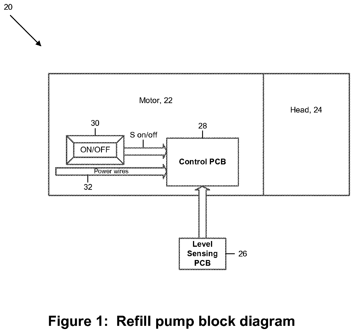
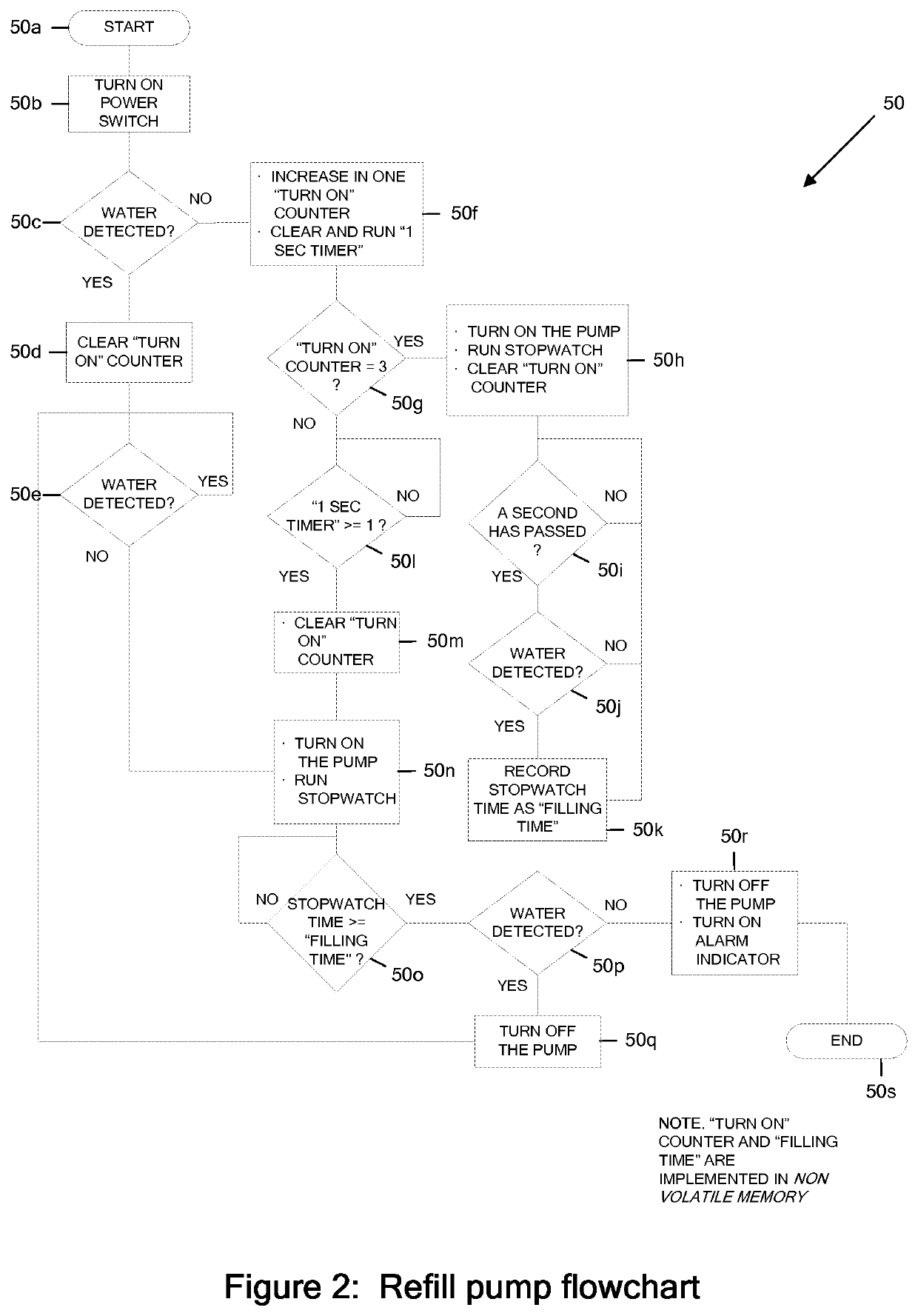
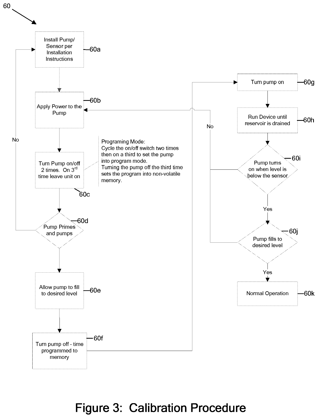
[0005]According to some embodiments, and by way of example, the present invention may include, or take the form of, apparatus featuring a signal processor, microcontroller, or signal processing module configured at least to:[0006]receive signaling containing information about a low level of a liquid sensed in an appliance reservoir to be supplied to an appliance that uses the liquid to dispense a flavored beverage, and also about when the appliance reservoir is refilled based upon an indication that forms part of an appliance reservoir refill level calibration procedure programmed by an appliance user; and[0007]determine corresponding signaling containing information about automatically refilling the liquid in the appliance reservoir, based upon the signaling received.

[0008]By way of example, the apparatus may include one or more of the following features:

[0009]The signal processor, microcontroller or signal processing module may be configured to:[0010]respond to associated signalin...


PUM


Abstract

A pump includes a signal processor that receives signaling containing information about a low level of a liquid sensed in an appliance reservoir to be supplied to an appliance that uses the liquid to dispense a flavored beverage, and also about when the appliance reservoir is refilled based upon an indication that forms part of an appliance reservoir refill level calibration procedure programmed by an appliance user; and determines corresponding signaling containing information about automatically refilling the liquid in the appliance reservoir, based upon the signaling received.

Description

CROSS-REFERENCE TO RELATED APPLICATIONS[0001]This application claims benefit to provisional patent application Ser. No. 62 / 037,761, filed 15 Aug. 2014, which is incorporated by reference in their entirety.BACKGROUND OF THE INVENTION1. Field of Invention[0002]The present invention relates to a pump control technique; and more particularly to a pump control technique related to an automatic fill of a reservoir, e.g., for an appliance.2. Description of Related Art[0003]Devices or units that are known in the art and out in the field utilize pressure to shut a pump off when not in use. This means that the supplied appliance must have a solenoid valve installed to shut off the flow of water to the appliance. Upon the appliance shutting the solenoid valve, the pressure builds up and the unit shuts off. When the pressure is relieved the pump begins to pumps again. These units also are typically in contact with the water in the reservoir to determine the low level and when to start the refil...

Claims


Application Information

Patent Timeline
Patent Type & Authority Patents(United States)
IPC IPC(8): G05D9/12G05D9/00G05D7/06
CPCG05D7/06G05D9/12G05D7/0623G05D9/00A47J31/56
Inventor PHILLIPS, DAVID L.ESTRADA, JESUS
Owner FLOW CONTROL LLC
Why Eureka
Try Eureka