Tablet printing apparatus and tablet printing method
a technology of printing apparatus and tablet, which is applied in the direction of printing, typewriters, pharmaceutical product form changes, etc., can solve the problems of deteriorating print quality, likely drying of the nozzle and the nozzle around the nozzle, etc., and achieve the effect of maintaining print quality
- Summary
- Abstract
- Description
- Claims
- Application Information
AI Technical Summary
Benefits of technology
Problems solved by technology
Method used
Image

Examples
first embodiment
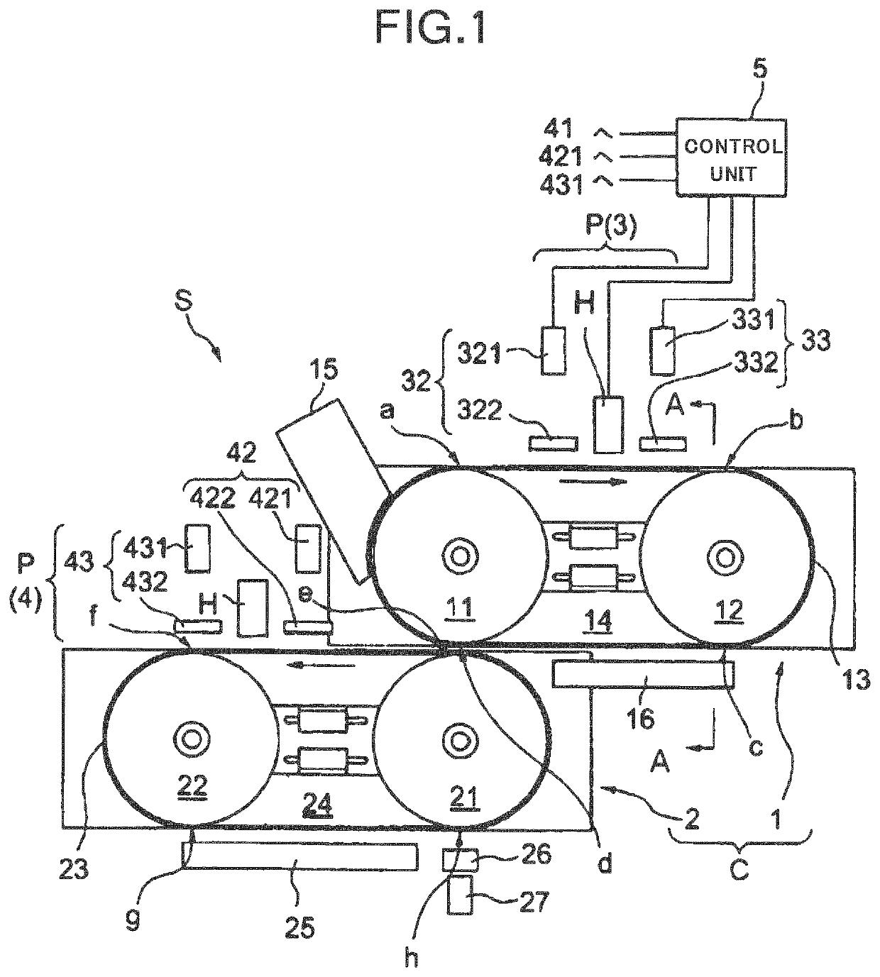
[0033]FIG. 1 is a front view illustrating the overall configuration of a tablet printing apparatus S according to a first embodiment. The tablet printing apparatus S includes a conveyor C for conveying tablets to be printed and a printing unit P for printing on the tablets conveyed by the conveyor C.
[0034]As illustrated in FIG. 1, the tablet printing apparatus S is configured so that the conveyor C includes a first conveyor 1 and a second conveyor 2 which are arranged one above the other to perform printing on both sides of a tablet. The printing unit P includes a first printing unit 3 and a second printing unit 4. The first printing unit 3 is arranged so as to face the first conveyor 1, and the second printing unit 4 is arranged so as to face the second conveyor 2. That is, the first printing unit 3 is located above the first conveyor 1, and the second printing unit 4 is located above the second conveyor 2. Thus, the tablet printing apparatus S as a whole is constituted.
[0035]In fi...
second embodiment
[0121]Next, a second embodiment, will be described with reference to FIGS. 7 to 14. In the second embodiment, like reference numerals designate like constituent elements as those described in the first embodiment, and the same description will not be repeated.
[0122]In the first embodiment described above, the suction force applied to the tablet T in the first region where printing is performed is lower than that applied to the tablet T in the second region, thereby preventing the occurrence of mist and printing defects due to an airflow caused by the suction of air in the suction portions 130.
[0123]On the other hand, in the second embodiment, in order to reduce the suction force applied to the tablet T in the first region without changing the suction force generated by the suction chamber 14, the following method is adopted. This method will be described in order with reference to FIGS. 7 and 8.
[0124]The suction force generated by the suction chamber 14, for example, is generated in...
third embodiment
[0156]Next, a third embodiment will be described with reference to FIGS. 15 to 17. In the third embodiment, like reference numerals designate like constituent elements as those described in the first embodiment or the second embodiment, and the same description will not be repeated.
[0157]In the first and second embodiments described above, the suction chamber 14 is divided into sections to reduce the suction force in a desired portion, or the suction force applied to the tablet T by the suction chamber 14 is reduced by limiting the airflow rate in a desired portion by using the suction force lowering member. On the other hand, in the third embodiment, a shielding member is provided to reduce the influence of the airflow generated around the tablet T when the suction chamber 14 sucks air.
[0158]FIGS. 15 and 16 are cross-sectional views of the tablet printing apparatus S as viewed from the front illustrating an enlarged view of an example of the shielding member according to the third ...
PUM
 Abstract
Description
Claims
Application Information
 - R&D
- Intellectual Property
- Life Sciences
- Materials
- Tech Scout
- Unparalleled Data Quality
- Higher Quality Content
- 60% Fewer Hallucinations
Browse by: Latest US Patents, China's latest patents, Technical Efficacy Thesaurus, Application Domain, Technology Topic, Popular Technical Reports.
© 2025 PatSnap. All rights reserved.Legal|Privacy policy|Modern Slavery Act Transparency Statement|Sitemap|About US| Contact US: help@patsnap.com