

Vessel electrical penetration assembly for a nuclear reactor
a nuclear reactor and electrical penetration technology, applied in electrical devices, nuclear energy generation, climate sustainability, etc., can solve the problems of not being very flexible, not very transposable directly to the smr field, and limited useful diameter
Active Publication Date: 2020-12-08
SOC TECH POUR LENERGIE ATOMIQUE TECHNICATOME
View PDF23 Cites 0 Cited by
- Summary
- Abstract
- Description
- Claims
- Application Information
AI Technical Summary
Benefits of technology
The solution enables flexible and safe electrical connections that meet the needs of SMR while adhering to design regulations, minimizing leakage risks and simplifying safety inspections by using a leaktight electrical bar and connectors that are not part of the primary containment barrier, thus reducing the complexity and risk associated with large-diameter assemblies.
Problems solved by technology
However, these solutions are not very transposable directly to the SMR field because, in practice, they do not meet the connection needs of a vessel actuator of an SMR.
In fact the very principle of the thimble does not able dismantleability at the level of the actuator, these solutions are not very flexible, and have a useful diameter limited to a typical value below 15 mm.
This approach only partially responds to the problem posed.
On the one hand, it may be considered disadvantageous for the overall design of the reactor to add a dismantleable vessel flange with the associated risk of leakage on this large diameter leaktight assembly.
On the other hand, the large number of electrical connections required by the putting in place of in-vessel actuators is going to lead to adopting either a very large number of thimbles of limited diameter, or thimbles of significantly larger diameter than those employed to date, said thimbles being dismantleable at the level of the actuators.
In each of these alternatives, this is going to complicate the safety demonstration and put constraints on the regulatory inspection of said second barrier extension.
Method used
View moreImage
Smart ImageViewing Examples

Examples
first embodiment
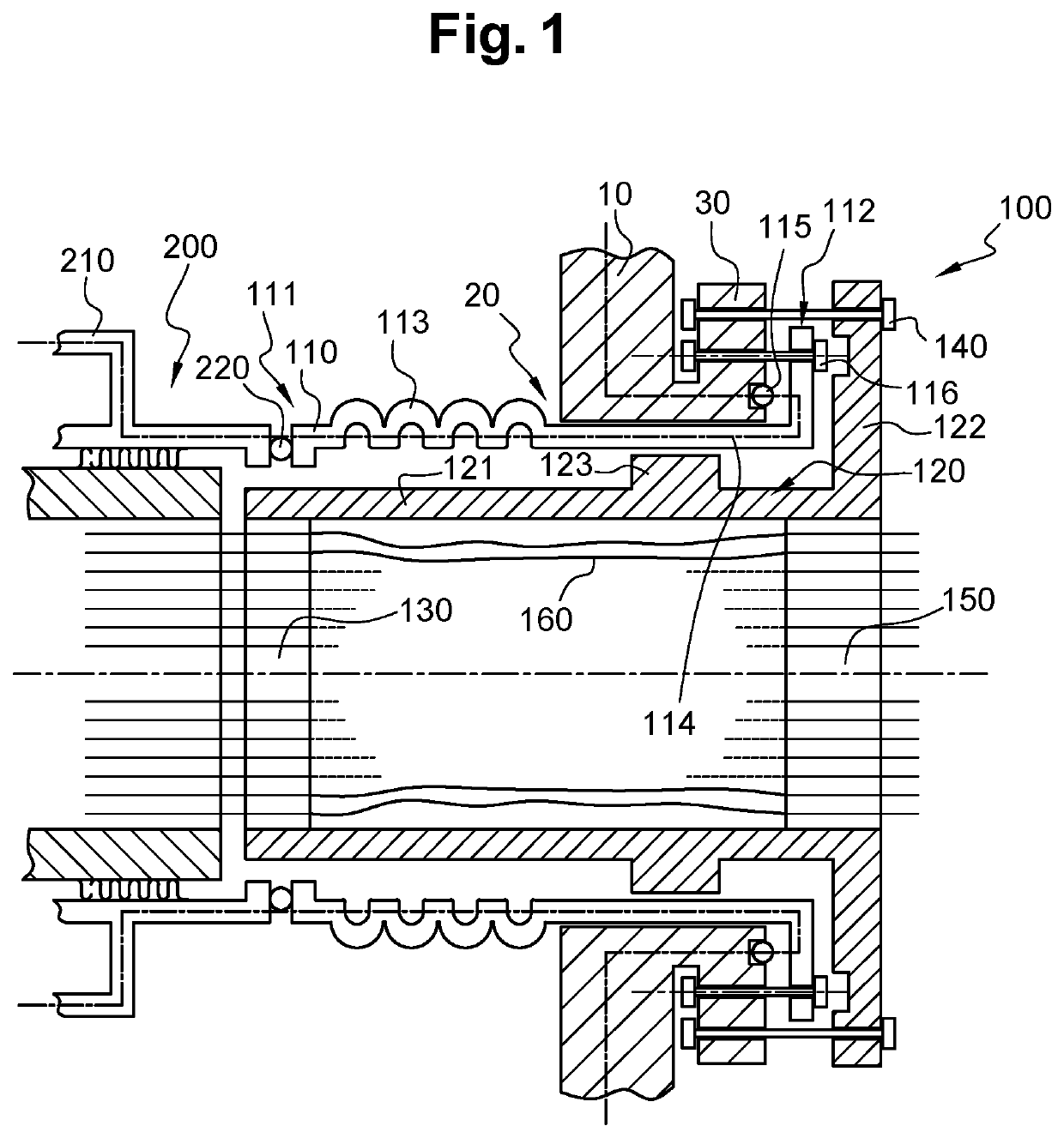
[0032]FIG. 1 illustrates a sectional view of a part of a vessel of a nuclear reactor showing a vessel electrical penetration assembly according to the invention.
second embodiment
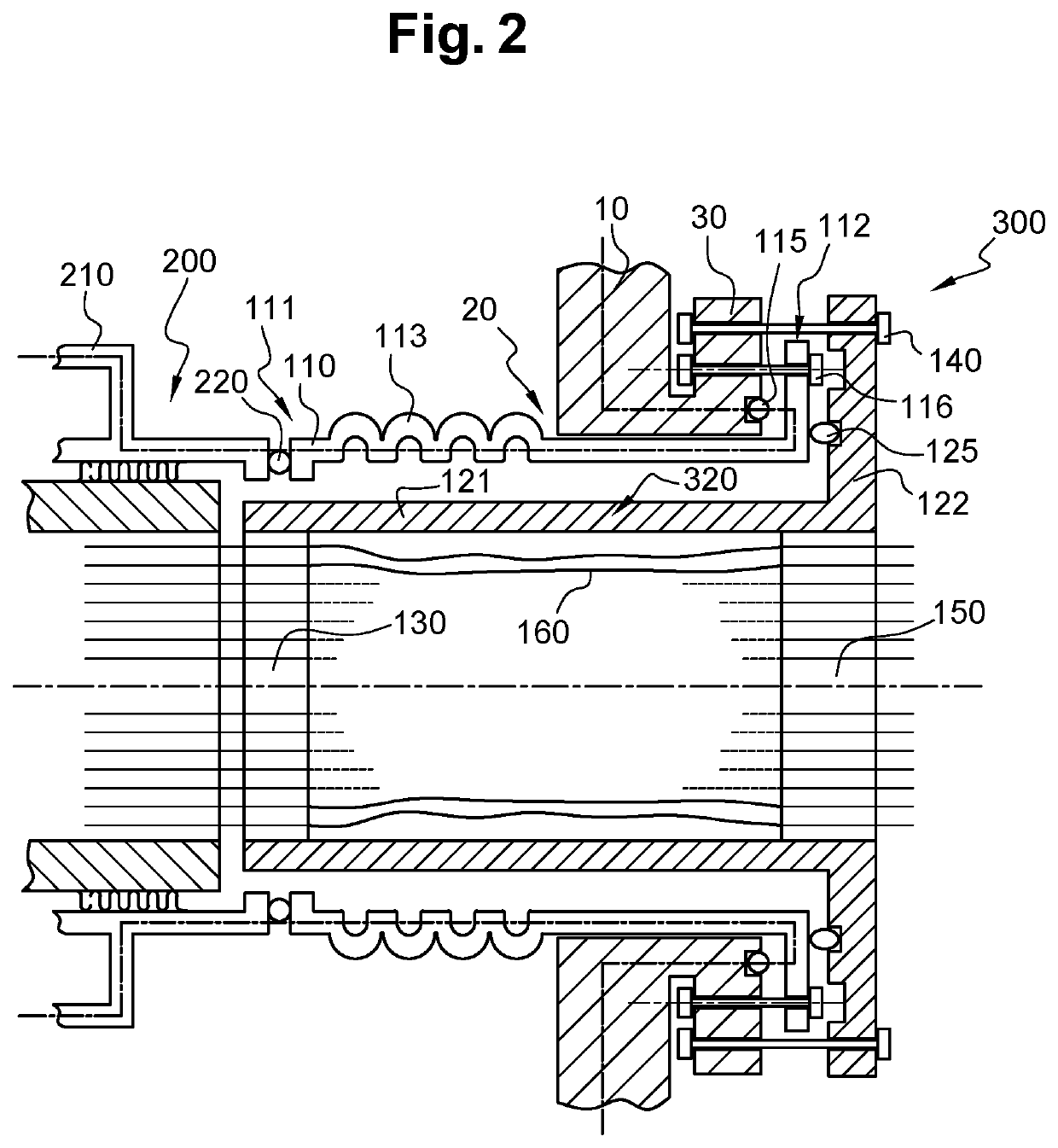
[0033]FIG. 2 illustrates a sectional view of a part of a vessel of a nuclear reactor showing a vessel electrical penetration assembly according to the invention.
third embodiment
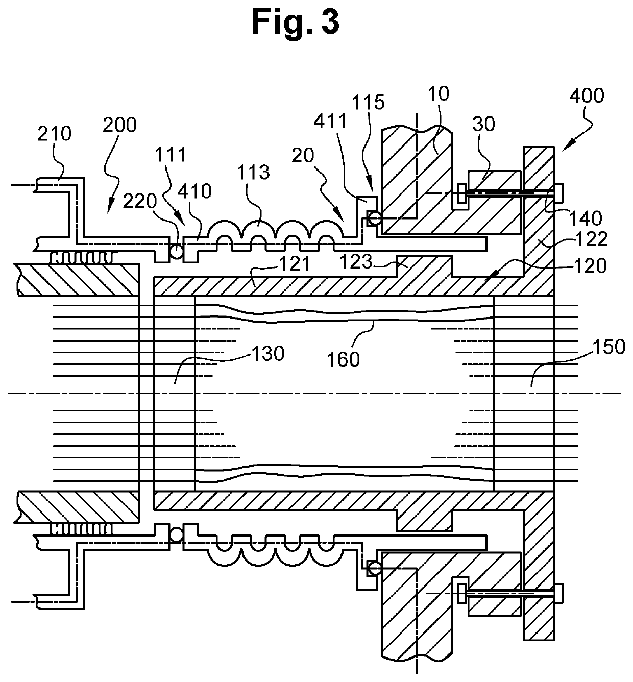
[0034]FIG. 3 illustrates a sectional view of a part of a vessel of a nuclear reactor showing a vessel electrical penetration assembly according to the invention.
[0035]The terms “upstream” and “downstream” used in the patent application are defined by considering the direction of flow of the primary fluid in the event of leakage, that is to say from the inside to the outside of the vessel 10.
Login to View More PUM
 Abstract
A vessel electrical penetration assembly for a feed-through of nuclear reactor vessel, the assembly including: a docking tube to form an extension of the secondary containment barrier of the reactor, the docking tube including: a first end to be positioned in the interior of the vessel and to be mechanically and sealably connected to an actuator in the interior of the vessel, and a second end to be mechanically and sealably secured to the vessel; a seal-tight electrical bar that passes through the docking tube and having on either side seal-tight connectors ensuring an electrical link between the actuator and the exterior of the reactor; the seal-tight electrical bar including a system for limiting a leakage of primary liquid to the exterior of the vessel if the secondary containment barrier extension fails; and a mechanical maintaining system for securing, under the required pressure conditions, the electrical bar to the vessel.
Description
CROSS-REFERENCE TO RELATED APPLICATIONS[0001]This is the U.S. National Stage of PCT / EP2016 / 074704, filed Oct. 14, 2016, which in turn claims priority to French Application No. 1561112, filed Nov. 19, 2015, the entire contents of all applications are incorporated herein by reference in their entireties.TECHNICAL FIELD OF THE INVENTION[0002]The invention relates to the field of vessel electrical penetration assemblies (V-EPA) passing through nuclear reactor vessels.[0003]The invention finds particularly interesting application in the field of integrated nuclear reactors and Small & Modular Reactors (SMR) comprising numerous in-vessel actuators / sensors creating specific electrical penetration needs. An application in conventional pressurised reactors is possible.PRIOR ART[0004]For an application in an SMR using in-vessel actuators, these vessel electrical penetrations have to meet several criteria. They must be able to be dismantled rapidly, be supple in order to be compatible with dif...
Claims
Login to View More Application Information
Patent Timeline
 Patent Type & AuthorityPatents(United States)
IPC IPC(8): G21C17/116G21C13/036H02G3/22G21F7/005
CPCG21C17/116G21C13/036G21F7/005H02G3/22Y02E30/30
InventorBRUN, MICHEL
OwnerSOC TECH POUR LENERGIE ATOMIQUE TECHNICATOME