Miter jig

a technology of miter joints and jigs, which is applied in the direction of drill jigs, metal working devices, manufacturing tools, etc., can solve the problems of little use of traditional miter joints and the devices used to make them

Active Publication Date: 2020-12-15
ZOBELL CORY
View PDF4 Cites 0 Cited by
  • Summary
  • Abstract
  • Description
  • Claims
  • Application Information

AI Technical Summary

Benefits of technology

[0006]Implementations of a miter jig are provided. The miter jig can be used to fabricate a non-perpendicular miter joint, the miter joint being formed by beveling each of two parts (e.g., wooden panels) to be joined to form a corner. By using the miter jig, each of the parts to be joined can be cut to have a bevel angle of up to 80°. In this way, a corner having an acute angle or an obtuse angle can be fabricated.

Problems solved by technology

But traditional miter joints, and the devices used to make them, are of little use when trying to join two parts to form a non-perpendicular corner.

Method used


Image

  • Miter jig
  • Miter jig
  • Miter jig

Examples


Embodiment Construction

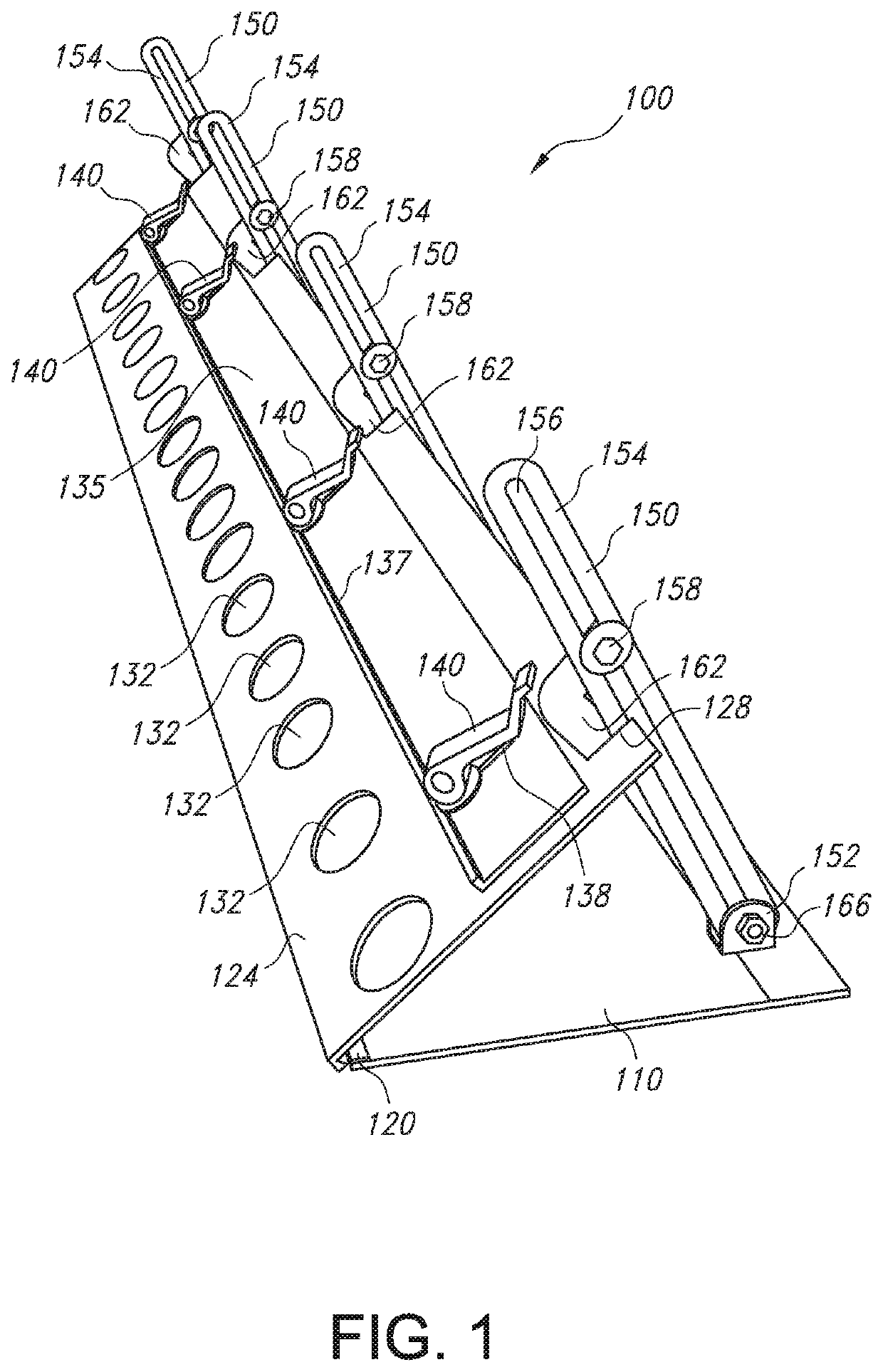
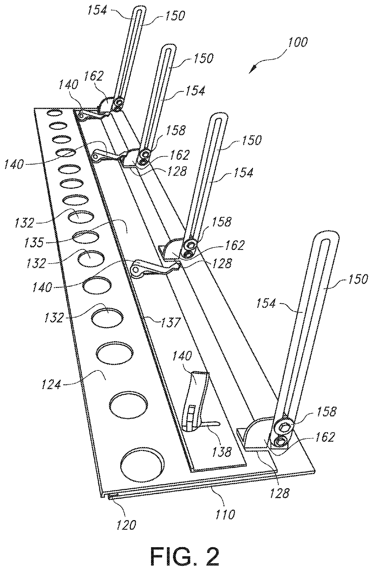
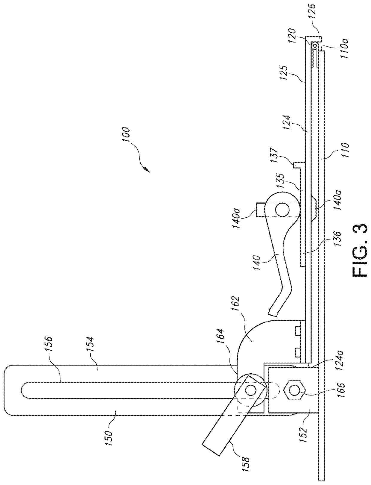
[0026]FIGS. 1-3 illustrate an example miter jig 100 according to the principles of the present disclosure. In some implementations, the miter jig 100 can be used to fabricate a non-perpendicular miter joint, the miter joint being formed by beveling each of two parts (e.g., wooden panels) to be joined to form a corner. In some implementations, by using a miter jig 100, each of the parts to be joined can be cut to have a bevel angle of up to 80°. In this way, for example, cabinets can be fabricated for installation on two intersecting walls forming a non-perpendicular corner.

[0027]As shown in FIGS. 1-3, in some implementations, the miter jig 100 is configured so that it can be secured to a workpiece and may comprise a base plate 110 connected to a top plate 124 by a piano hinge 120, four adjustable brace assemblies 150 used to adjust (and set) the angle of the top plate 124 relative to the base plate 110, and a router guide 135 configured to guide a cutting implement to cut a workpiec...


PUM


Abstract

Implementations of a miter jig are provided. The miter jig can be used to fabricate a non-perpendicular miter joint, the miter joint being formed by beveling each of two parts (e.g., wooden panels) to be joined to form a corner. By using a miter jig, each of the parts to be joined can be cut to have a bevel angle of up to 80°. In this way, a corner having an acute angle or an obtuse angle can be formed. The miter jig is configured so that it can be secured to a workpiece and comprises a base plate connected to a top plate by a hinge, at least two adjustable brace assemblies configured to set the angle of the top plate relative to the base plate, and a cutting implement guide configured to guide a cutting implement to cut a workpiece at an angle.

Description

CROSS REFERENCE TO RELATED APPLICATION[0001]This application claims the benefit of U.S. Provisional Application Ser. No. 62 / 614,543, which was filed on Jan. 8, 2018, and is incorporated herein by reference in its entirety.TECHNICAL FIELD[0002]This disclosure relates to implementations of a jig used to fabricate miter joints. In particular, the present invention is directed to implementations of a jig that may be used to fabricate non-perpendicular miter joints.BACKGROUND[0003]Mitered joints are often used because they provide aesthetically pleasing joints. A miter joint is used to join two parts (e.g., two pieces of wood or other material) together to form a corner. Typically, a miter joint is a joint occurring at an angle of 90° that is made by beveling each of two parts to be joined, usually at a 45° angle. But traditional miter joints, and the devices used to make them, are of little use when trying to join two parts to form a non-perpendicular corner.[0004]Buildings, furniture, ...

Claims


Application Information

Patent Timeline
Patent Type & Authority Patents(United States)
IPC IPC(8): B27G5/00B23Q9/00B27G5/02B23B47/28
CPCB27G5/026B23Q9/005B23B47/287
Inventor ZOBELL, CORY
Owner ZOBELL CORY
Why Eureka
Try Eureka