Mushroom-compaction and asymmetric-thread impact-drivable screw

a technology of driveable screws and mushroom fibers, applied in the direction of screws, fastening means, nails, etc., can solve the problems of screw ripping and tearing wood fibers, time-consuming, and difficult if not impossible disassembly, and achieve the effect of minimizing the cutting or breaking of wood fibers and increasing gripping strength

Active Publication Date: 2020-12-15
LITZINGER W C
View PDF60 Cites 2 Cited by
  • Summary
  • Abstract
  • Description
  • Claims
  • Application Information

AI Technical Summary

Benefits of technology

[0010]The present invention is directed to an improved screw nail. In accordance with one exemplary embodiment of the present invention, an asymmetric thread impact drivable screw is provided using an impact head and a conical shaped tip having a ballistic insertion angle formed on the ends of a shank defining an axis. Of particular note is the use of the ballistic tip with the shank defining asymmetrical threads. The ballistic tip and the threads have a unique shape adapted for dividing the wood fibers while minimizing the cutting or breakage of the wood fibers. The thread has an insertion flank protruding from the shank at slide angle to push the fibers aside and allow for penetration of the wood without cutting the fibers. The slide angle has a long surface area leading to a crest that is supported on the back side by a catch flank. The catch flank is protruding from the shank at an impact supporting grip angle that provides the necessary support to the crest during impact insertion while still providing increased gripping strength when compared to bare nail shanks.

Problems solved by technology

This is very time consuming because of the extended time period it takes to rotate the screw into the material.
Similarly, the use of regular nails creates a strong bind that is difficult if not impossible to disassemble.
These screws rip and tear the wood fibers during installation.
ertion. Thus, it may be seen that these prior art patents are very limited in their teaching and utilization, and an improved impact driveable screwnail is needed to overcome these limi

Method used


Image

  • Mushroom-compaction and asymmetric-thread impact-drivable screw
  • Mushroom-compaction and asymmetric-thread impact-drivable screw
  • Mushroom-compaction and asymmetric-thread impact-drivable screw

Examples


Embodiment Construction

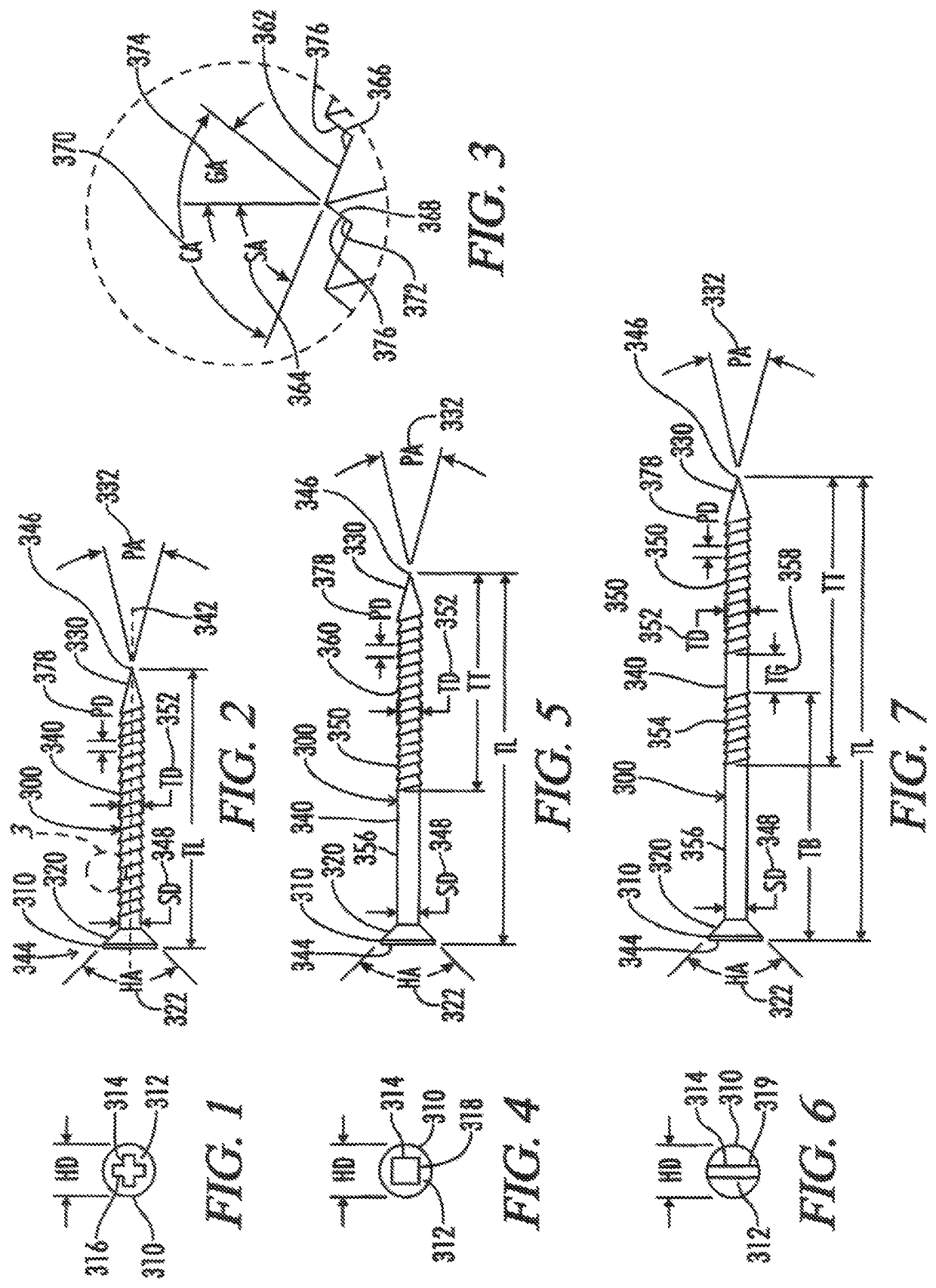
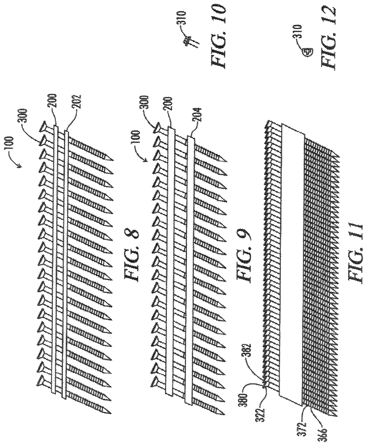
[0031]As shown in FIGS. 8 and 9 of the drawings, exemplary embodiments of the present invention are generally shown as an asymmetric thread impact drivable screw clips 100 having asymmetric thread impact drivable screws 300 connected by a collating strip 200. The collating strip 200 may be made from any conventional material including wire, paper, plastics, epoxies, or other known materials and is typically made from a wire 202 as shown in FIG. 8, or a plastic strip 204 as shown in FIG. 9. Strips, sheets, lines, and other known collating schemes may be used with the present invention. Alternative embodiments may include coiled strips, ratcheting strips, or other constructions.

[0032]As shown in FIGS. 1 through 9, the asymmetric thread impact drivable screw 300 has an impact head 310 with a top surface 312 having a head diameter HD defining a tool receiving recess 314. The counter sunk head shown is the preferred design, although any of the other head types may be implemented if it is...


PUM

PropertyMeasurementUnit
ballistic insertion angleaaaaaaaaaa
grip angleaaaaaaaaaa

Abstract

An asymmetric thread impact drivable screw and clip for use with a power impact device for penetrating wood fibers while minimizing cut fibers. The screw includes an impact head and a conical shaped tip having a ballistic insertion angle at the ends of a shank. The shank defines asymmetrical threads with an insertion flank having a long side at a slide angle peaking at a crest supported by a catch flank positioned at a grip angle. Varying tool accepting recess are taught for the head along with multiple thread sections. A mushroom compaction thread section is also taught.

Description

CROSS-REFERENCE TO RELATED APPLICATIONS[0001]This application claims priority to and is a continuation-in-part of U.S. patent application Ser. No. 15 / 070,316, filed on Mar. 15, 2016 entitled Mushroom-Compaction and Asymmetric-Thread Impact-Drivable Screw, which claims priority to and is a continuation-in-part of U.S. patent application Ser. No. 14 / 189,551, filed on Feb. 25, 2014 entitled Mushroom-Compaction and Asymmetric-Thread Impact-Drivable Screw, which claims priority to and is a continuation-in-part of U.S. patent application Ser. No. 12 / 807,500, filed on Sep. 27, 2010 entitled Mushroom-compaction Asymmetric-Thread Impact-Drivable Screw which is a continuation in part of U.S. patent application Ser. No. 11 / 725,967, filed on Mar. 20, 2007, which is a continuation in part of both U.S. Provisional Application Ser. No. 60 / 790,501 filed by Litzinger on Apr. 7, 2006 entitled Asymmetric Thread Impact Drivable Screw and U.S. Provisional Application Ser. No. 60 / 854,884 filed by Litzing...

Claims


Application Information

Patent Timeline
Patent Type & Authority Patents(United States)
IPC IPC(8): F16B15/00F16B25/00F16B15/08F16B25/10F16B15/06
CPCF16B25/0042F16B15/08F16B15/06F16B25/106F16B25/0015F16B25/0047F16B25/0057F16B25/0063F16B25/0084
Inventor LITZINGER, W. C.
Owner LITZINGER W C
Why Eureka
Try Eureka