Collision obstacles and sensors for determining the outcome of a race

a technology of sensors and obstacles, applied in toys, toy trackways, entertainment, etc., to achieve the effect of reducing the labor required of the raceway owner or operator, simplifying the installation requirements of sensors, and reducing the cost of sensor apparatuses

Inactive Publication Date: 2007-10-23
TULLIS BARCLAY J +1
View PDF8 Cites 30 Cited by
  • Summary
  • Abstract
  • Description
  • Claims
  • Application Information

AI Technical Summary

Benefits of technology

[0012]A freestanding collision obstacle is disclosed which is propelled away from a collision obstacle sensing apparatus by the force of a collision event that occurs when a moving object, for example a toy vehicle such as a racecar, collides with the collision obstacle. A collision obstacle sensing apparatus is disclosed which incorporates a collision obstacle and a collision obstacle sensor, the latter of which senses the presence or absence of the collision obstacle. The collision obstacle sensing apparatus can be used to detect an event time as the time of a collision event. Use of a collision obstacle and a collision obstacle sensing apparatus in each lane at the finish line of a multilane raceway, with the moving objects individually confined to respective lanes of the raceway, enables electronic determination of the outcome of a race. Preferred embodiments are disclosed using optical and / or capacitance sensors.
[0013]A first objective of this invention is to reduce the cost of sensor apparatuses used to sense the crossing of toy vehicles (e.g. racecars) across a finish line wherein each vehicle is confined to travel in a respective lane of a raceway (e.g. a racetrack). A second objective is to simplify sensor installation requirements on a raceway by reducing the labor required of the raceway owner or operator and by minimizing drilling and / or cutting required installing such sensor apparatuses on the raceway. A third objective is to simultaneously add a new component of action and excitement to vehicle races with the addition of collision interaction between racing vehicles and collision objects placed in the paths of these vehicles at the finish line.
[0014]Certain objects, advantages and novel features of the invention will be set forth in part in the description that follows and in part will become apparent to those skilled in the art upon examination of the following or may be learned with the practice of the invention. The objects and advantages of the invention may be realized and obtained by means of the methods and apparatuses and combinations particularly pointed out in the appended claims.
[0015]The objects of the invention are principally to provide apparatuses, for sensing finish line events, that a) are low in cost, b) can be installed on a racetrack or other raceway without cutting large or complicated holes, c) permit precise and accurate sensing of finish line events (to at least +−0.001 sec), d) are convenient to use, e) remain protected from effects of ambient lighting conditions on the photosensor, and f) actually add excitement to the race experience. The object of the invention is also to provide methods for sensing finish line events in manners that are simple to learn and carry out and that prevent set-up and operation from having variable influence on race results.
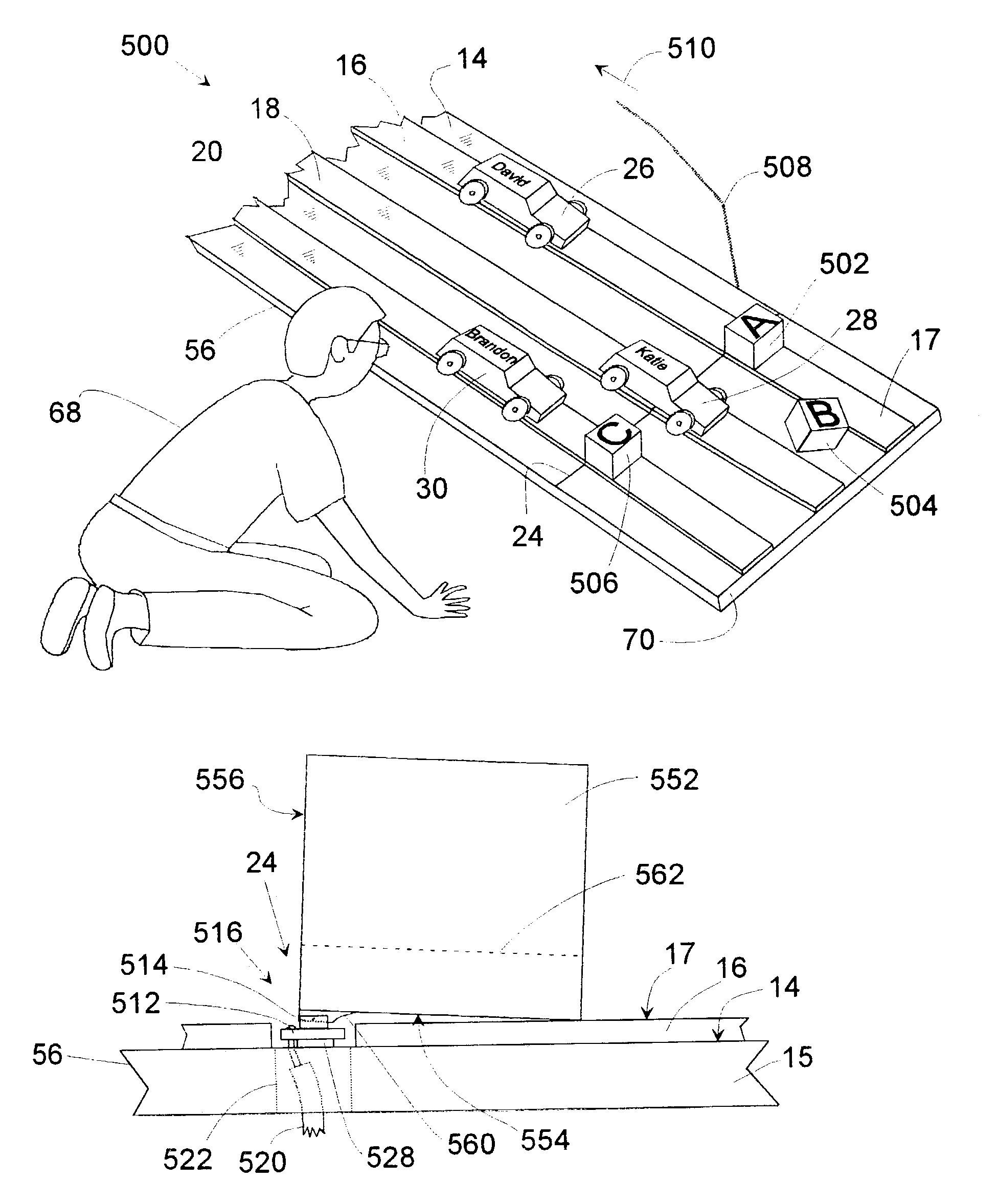
[0016]These and other objects of the invention are provided by a novel use of a freestanding collision obstacle comprising: a) a collision surface that can be positioned and oriented to make first contact with a moving object; b) a sensor-interaction feature capable of interaction with a stationary sensor; c) a base supporting both said collision surface and said sensor-interaction feature; wherein said freestanding collision obstacle is a free collision obstacle; and wherein said stationary sensor is located beneath said collision obstacle prior to a collision.
[0017]For each lane in a racetrack (or other raceway) along which a racecar travels (or along which some other moving object travels), a freestanding collision obstacle is placed to rest over a sensor that is anchored to the racetrack (e.g. to the structure of the racetrack, such as on, in, and / or below a race surface of a racetrack). The collision obstacle includes a sensor interacting feature. Before a race, the collision obstacle is positioned such that this sensor interacting feature interacts with the sensor. If the sensor used is a slotted photosensor, and if the sensor interacting feature is an optically opaque flag, then the optically opaque flag is positioned in the slot of the slotted photosensor before a race. As moving objects (such as racecars) cross the finish line, they each collide with a respective collision obstacle and knock it free of the sensor it is positioned over (i.e. that with which it is associated), thus causing the sensor-interaction feature to leave the sensor. As a collision obstacle leaves its associated sensor, the sensor experiences a change in its sensing condition, thus determining an electronic event in the sensor. If the sensor used is a slotted photosensor, and if the sensor interacting feature is an optically opaque flag, then a collision with the collision obstacle knocks the optically opaque flag out of the slot in the slotted photosensor. Note that if a slotted photosensor is used, then until a collision occurs to knock the associated collision obstacle away, the collision obstacle can effectively block ambient light from entering the slotted photosensor, a definite advantage over prior art arrangements using photosensors exposed to ambient light.

Problems solved by technology

As moving objects (such as racecars) cross the finish line, they each collide with a respective collision obstacle and knock it free of the sensor it is positioned over (i.e. that with which it is associated), thus causing the sensor-interaction feature to leave the sensor.

Method used


Image

  • Collision obstacles and sensors for determining the outcome of a race
  • Collision obstacles and sensors for determining the outcome of a race
  • Collision obstacles and sensors for determining the outcome of a race

Examples


Embodiment Construction

[0046]Having summarized various aspects of the present invention, reference will now be made in detail to the description of the invention and its relation to prior art, both as illustrated in the drawings. While the invention will be described in connection with these drawings, there is no intent to limit it to the embodiment or embodiments disclosed therein. On the contrary, the intent is to cover all alternatives, modifications and equivalents included within the spirit and scope of the invention as defined by the appended claims.

[0047]Reference will first be made to FIG. 1 and FIG. 2 that illustrate a racetrack along with elements important to the conduct of a race using the prior art in what is referred to as a completely manual mode of operation. Reference will then be made to FIG. 3 that shows a block diagram of an electronic system that uses sensors installed on a track to detect the moments racecars are released at a start line and later cross a finish line. Reference will ...


PUM


Abstract

A freestanding collision obstacle is disclosed which is propelled away from a collision obstacle sensing apparatus by the force of a collision event that occurs when a moving object, for example a toy vehicle such as a racecar, collides with the collision obstacle. A collision obstacle sensing apparatus is disclosed which incorporates a collision obstacle and a collision obstacle sensor, the latter of which senses the presence or absence of the collision obstacle. The collision obstacle sensing apparatus is thus used to detect an event time as the time of a collision event. Use of a collision obstacle and a collision obstacle sensing apparatus in each lane at the finish line of a multilane raceway, with the moving objects individually confined to respective lanes of the raceway, enables electronic determination of the outcome of a race. Preferred embodiments are disclosed using optical and/or capacitance sensors.

Description

CROSS-REFERENCE TO RELATED APPLICATIONS[0001]Not ApplicableFEDERALLY SPONSORED RESEARCH[0002]Not ApplicableSEQUENCE LISTING OR PROGRAM[0003]Not ApplicableBACKGROUND OF THE INVENTION[0004]1. Field of the Invention[0005]This invention generally pertains to a sensing means by which to determine the moment in time that a moving object collides with a collision obstacle that is in cooperative association with a stationary sensor. It particularly pertains to a low-cost sensing apparatus for sensing the arrival of one or more toy vehicles (e.g. racecars) across the finish line on a raceway (e.g. a racetrack).[0006]2. Description of Related Art[0007]There are no prior art methods, structures, apparatuses, or devices published or on the market for utilizing a free collision obstacle in the path of a moving vehicle to electronically sense the arrival of the vehicle at a finish line. Within this disclosure, the meaning of “free” in “free collision obstacle” is that a collision obstacle is not ...

Claims


Application Information

Patent Timeline
Patent Type & Authority Patents(United States)
IPC IPC(8): A63H18/00
CPCA63H18/026
Inventor TULLIS, BARCLAY J.
Owner TULLIS BARCLAY J
Why Eureka
Try Eureka