Diverging TIR facet LED optics producing narrow beams with color consistency

a technology of led optics and dipoles, applied in the field of led lighting systems, to achieve the effect of reducing or eliminating the effect of color over angle effects

Active Publication Date: 2020-12-22
KORRUS INC
View PDF24 Cites 0 Cited by
  • Summary
  • Abstract
  • Description
  • Claims
  • Application Information

AI Technical Summary

Benefits of technology

[0004]Various illustrative embodiments provide an LED optic which redirects light from an LED into a beam pattern wherein the light is mixed to mitigate or eliminate color over angle effects.

Problems solved by technology

Various undesirable non-uniformities such as yellow rings in the LED light output can result.

Method used


Image

  • Diverging TIR facet LED optics producing narrow beams with color consistency
  • Diverging TIR facet LED optics producing narrow beams with color consistency
  • Diverging TIR facet LED optics producing narrow beams with color consistency

Examples


Embodiment Construction

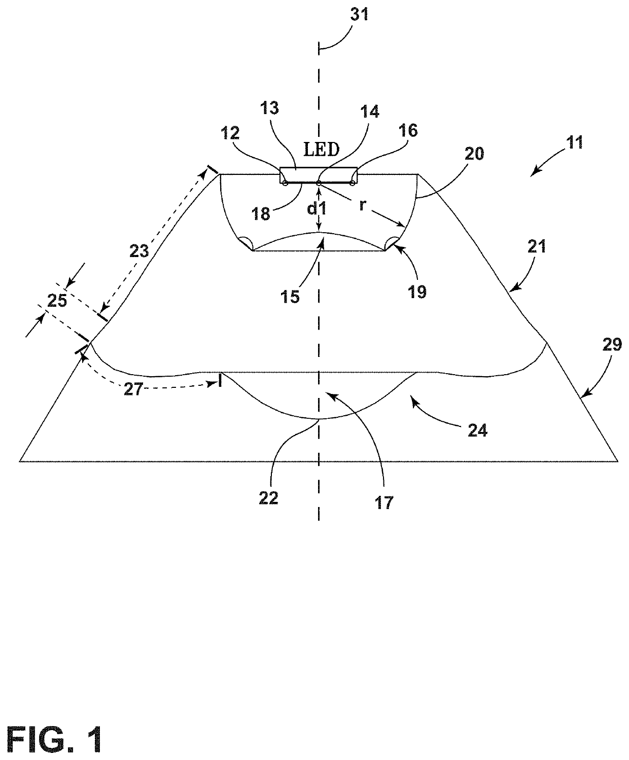
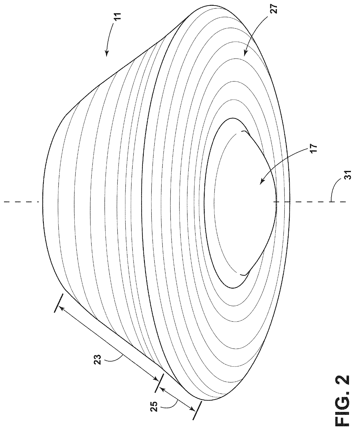
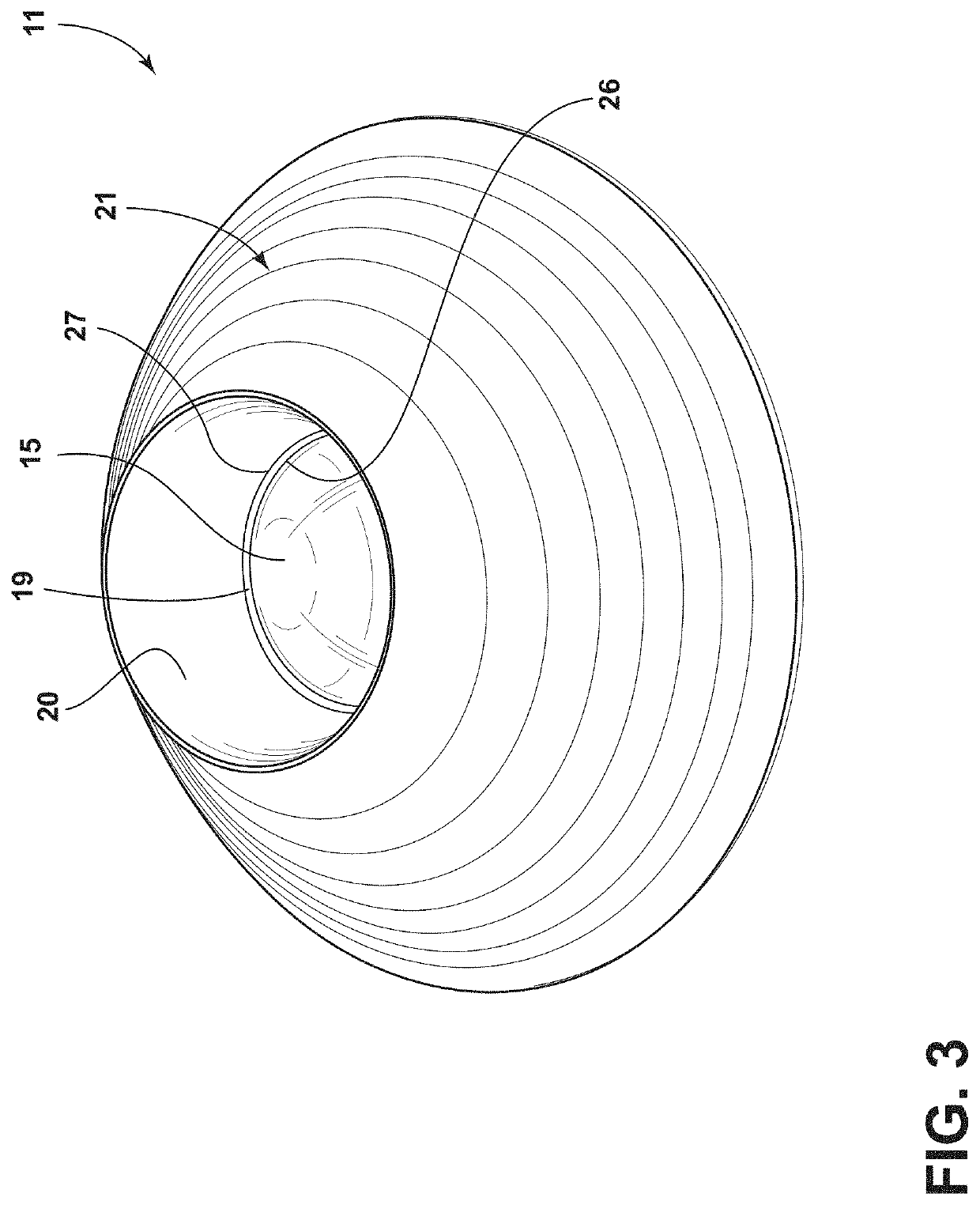
[0041]An illustrative LED optic 11 is shown in FIGS. 1-3 and comprises a first lens 15, a second lens 17, an upper collecting optic 20, a lower collecting lens 19, a TIR (“Total Internal Reflectance”) lens section 21, and an angle matched refracting lens 27. In an illustrative embodiment, the LED optic 11 is formed of a solid block of transparent material, for example, such as PMMA, for example, by injection molding processes.

[0042]In FIG. 1, an LED 13 is located above the first lens 15. The first lens 15 is positioned axially above the second lens 17, which is located at the lower end of the LED optic 11. The first lens 15 is radially surrounded by the lower collecting lens 19 and the upper collecting optic 20. For purposes of the illustrative embodiment, the front face 18 of the LED 13 is divided into three main points of light 12, 14, 16.

[0043]In an illustrative embodiment, the surface of the upper collecting optic 20 is located at a radius “r” from the center point of light 14, ...


PUM

PropertyMeasurementUnit
distance d1aaaaaaaaaa
angleaaaaaaaaaa

Abstract

An LED optic having a first lens positioned below an LED within a lower collecting lens at a top end of a TIR lens portion, the TIR lens portion having an array of flat diverging TIR facets, beneath which is located an array of parabolic beam reflecting TIR facets. A second lens is positioned beneath the first lens and the array of parabolic beam reflecting TIR facets and is surrounded by an angle-matched refracting lens formed at the lower end of the array of parabolic beam reflecting TIR facets.

Description

BACKGROUND OF THE DISCLOSUREField of the Disclosure[0001]The subject disclosure relates to lighting systems and in one example to LED lighting systems having an optic structure employing an array of diverging TIR facets acting in conjunction with an angle matched refractive output lens to shape and direct the light output of an LED device so as to mitigate color over angle effects.Description of Related Art[0002]LEDs (light emitting diodes) are now in widespread use in various lighting applications. In many applications, it is desirable to produce a light output from the LEDs which is of a uniform color. Achievement of uniform color is complicated by the so-called “color over angle effect.” As a result of this effect, the color of the light emitted by an LED can be dependent on the angle which the exiting light rays make with the surface of the LED. Various undesirable non-uniformities such as yellow rings in the LED light output can result.[0003]TIR (Total Internal Reflectance) opt...

Claims


Application Information

Patent Timeline
Patent Type & Authority Patents(United States)
IPC IPC(8): F21V13/04F21V7/00F21V5/04F21Y115/10
CPCF21V5/04F21V13/04F21V7/0091F21Y2115/10G02B19/0061
Inventor LATSIS, CHRISPEARSON, DENNISBREMSER, MICHAEL D.LUEKEN, THOMAS
Owner KORRUS INC
Why Eureka
Try Eureka