Check patentability & draft patents in minutes with Patsnap Eureka AI!

Battery system, vehicle with such a battery system, and method for operation of such a battery system

a battery system and battery technology, applied in the direction of batteries, cell components, electrical equipment, etc., can solve problems such as significant safety risks

Active Publication Date: 2020-12-22
ROBERT BOSCH GMBH
View PDF7 Cites 0 Cited by
  • Summary
  • Abstract
  • Description
  • Claims
  • Application Information

AI Technical Summary

Benefits of technology

[0012]A battery system according to the invention offers the advantage that a temperature control of a battery module having a plurality of battery cells can be made available which, moreover, can be connected in straightforward manner and independently to a further temperature-control system such as, for instance, a temperature-control system of a vehicle.

Problems solved by technology

If, on the other hand, the battery cells exceed a specified safety-critical temperature, this can lead to a thermal runaway of the battery cell and to a possibly associated propagation, resulting in considerable safety risks.

Method used


Image

  • Battery system, vehicle with such a battery system, and method for operation of such a battery system

Examples


Embodiment Construction

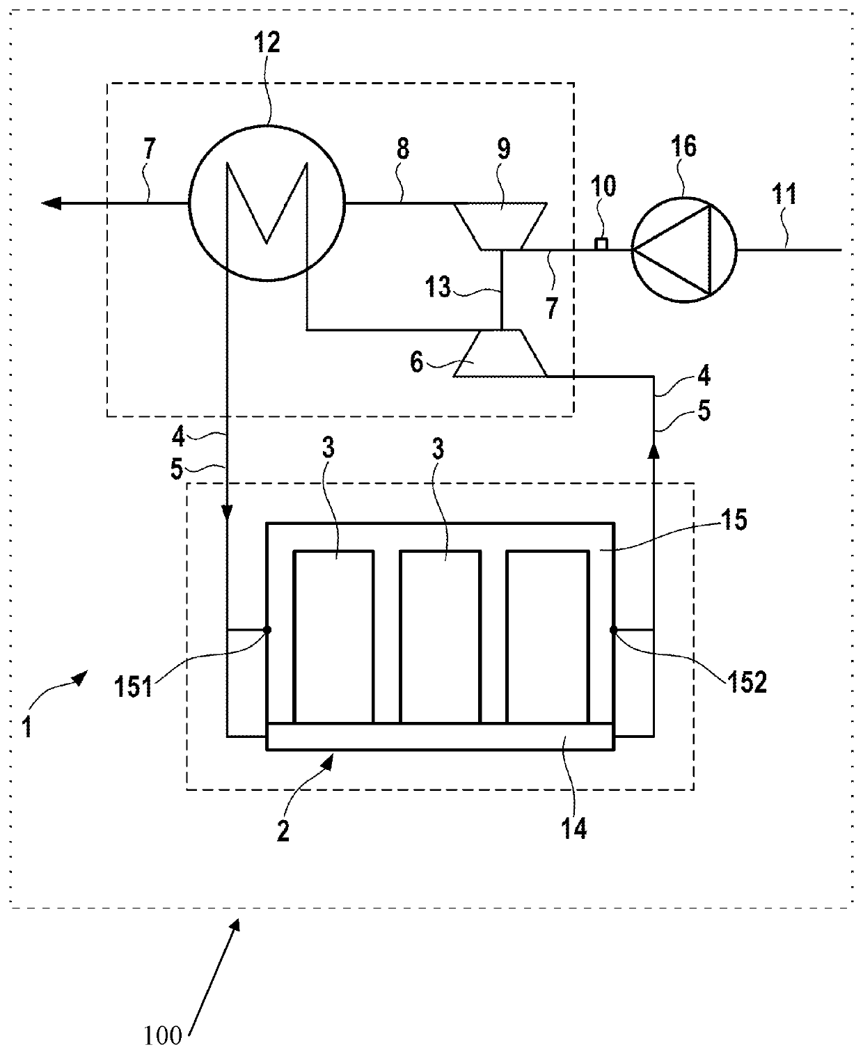
[0095]FIG. 1 shows schematically an embodiment of a battery system 1 according to the invention.

[0096]The battery system 1 may be, in particular, a battery system 1 of a vehicle 100 which is represented only schematically in FIG. 1.

[0097]The battery system 1 includes a battery module 2 which comprises a plurality of battery cells 3.

[0098]The plurality of battery cells 3 may take the form of, for instance, lithium-ion battery cells or lithium-polymer battery cells.

[0099]The battery system 1 exhibits a first temperature-control-fluid guide 4.

[0100]The first temperature-control-fluid guide 4 is designed to be capable of being flowed through by a first temperature-control fluid 5.

[0101]In particular, a first temperature-control fluid 5 is received in the first temperature-control-fluid guide 4.

[0102]The first temperature-control fluid 5 may take the form of a water / glycol mixture or a dielectric temperature-control fluid.

[0103]The first temperature-control-fluid guide 4 exhibits, moreov...


PUM

PropertyMeasurementUnit
operating temperatureaaaaaaaaaa
temperatureaaaaaaaaaa

Abstract

The invention relates to a battery system with a battery module (2) comprising a plurality of battery cells (3), wherein the battery cells (3) take the form, in particular, of lithium-ion battery cells or lithium-polymer battery cells, wherein the battery system (1) exhibits a first temperature-control-fluid guide (4) which is designed to be capable of being flowed through by a first temperature-control fluid (5) and, moreover, exhibits a first conveying unit (6) designed for a conveyance of the first temperature-control fluid (5) through the first temperature-control-fluid guide (4), and wherein the first temperature-control-fluid guide (4) is connected to the battery module (2) in heat-conducting manner, wherein the battery system (1) exhibits a second temperature-control-fluid guide (7) which is designed to be capable of being flowed through by a second temperature-control fluid (8) and, moreover, exhibits a second conveying unit (9) designed for an uptake of kinetic energy from the second temperature-control fluid (8), wherein the second temperature-control-fluid guide (7) exhibits at least one port (10) designed for a fluid-conducting connection to a further temperature-control-fluid guide (11), wherein the battery system (1) exhibits, moreover, a heat-exchanger unit (12) designed to the first temperature-control-fluid guide (4) and to the second temperature-control-fluid guide (7) in heat-conducting manner, which is designed to transfer heat between the first temperature-control-fluid guide (4) and the second temperature-control-fluid guide (7), wherein the first conveying element (6) and the second conveying element (9) are connected to one another in coupled manner in such a way that mechanical work can be transferred from the second conveying element (9) to the first conveying element (6).

Description

BACKGROUND OF THE INVENTION[0001]The invention takes as its starting-point a battery system.[0002]Furthermore, the invention also relates to a vehicle including such a battery system.[0003]Also a subject of the present invention is a method for operating such a battery system.[0004]It is known from the state of the art that battery modules may consist of a plurality of individual battery cells which may have been interconnected in series and / or in parallel in electrically conducting manner.[0005]Particularly in the case of electrically-operated vehicles (EV), hybrid electric vehicles (HEV) or plug-in hybrid electric vehicles (PHEV), high-energy and high-powered battery modules comprising lithium-ion battery cells or lithium-polymer battery cells, which preferably exhibit around a hundred battery cells, are employed, in order to be able to satisfy heightened expectations in terms of performance.[0006]By reason of chemical conversion processes, the lithium-ion battery cells or lithium...

Claims


Application Information

Patent Timeline
Patent Type & Authority Patents(United States)
IPC IPC(8): H01M10/613H01M10/6568H01M2/10H01M10/0525H01M10/625H01M50/204
CPCH01M10/6568H01M10/0525H01M10/625H01M10/613H01M2/1077H01M2220/20H01M10/615H01M10/6556H01M50/204Y02E60/10
Inventor KOLLER, TORSTEN
Owner ROBERT BOSCH GMBH
Features
  • R&D
  • Intellectual Property
  • Life Sciences
  • Materials
  • Tech Scout
  • Unparalleled Data Quality
  • Higher Quality Content
  • 60% Fewer Hallucinations
Learn More