Fastening device for fastening elements

a technology of fastening device and fastening element, which is applied in the direction of ceilings, fastening means, mechanical apparatus, etc., can solve the problems of time-consuming and labor-intensive fastening operation, visual defects and drawbacks, and the prior art's fastening solution is not known. to achieve the effect of fastening the element and easy operation

Active Publication Date: 2020-12-29
INNVOLVE CAPITAL OY
View PDF23 Cites 4 Cited by
  • Summary
  • Abstract
  • Description
  • Claims
  • Application Information

AI Technical Summary

Benefits of technology

[0005]An object of the invention is to alleviate and eliminate the problems relating to the known prior art. Especially the object of the invention is to provide a device for fastening the elements easily and fast so that there are no needs to provide any screw holes to the elements or other structures, and additionally offering possibility to very freely build any combination from the elements. In addition due to the embodiments of the invention the elements can be reused, because the fastening method and fastening device according to the invention does not make any marks or holes or other tracks or damages to the elements.
[0009]The angle portion is advantageously inclined to extending towards the opening and intersecting a normal of said top planar portion at least in the end portion of said planar portion, whereupon the extent of the inclined angle portion determines the size of the opening for receiving the element. The angle portion offers advantage namely it prevents the planar top portion to be bent when the side portions are opened around the element to be fastened.
[0012]However, the protrusion portions according to the invention allow and make it possible to fasten the number of the devices with the elements to the external members via their magnetic members in a precise manner and to provide even large element combination with straight lines. It is to be noted that the external member may be e.g. another device or an external structure member, such as structure of a building, like a wall or roof structure member. Advantageously, if the device is fastened to another device or external structure member, another device or external structure member must be magnetic material, such as steel structure of the device or steel structure in the external structure member, such as a wall or a roof, for example. However, it is to be noted that according to an embodiment a first side of the magnet is configured to be faced against the device and the second side may comprise adhesive material, such as tape or glue, whereupon the device can be fastened to the external structure via the adhesive material even if the external structure would not comprise magnetic material at all.
[0018]The present invention offers advantages over the known prior art, such as possibility to easily and fast to fasten elements to each other via the devices or to another external structures, and especially so that there are no needs to provide any screw holes to the elements or other structures. Furthermore the embodiments of the invention offer possibility to very freely build any combination from the elements, as well as to modify also the complete combination already build, which is clear advantage in many cases, because there is no need e.g. to dismantle the structure combination or unscrew the bolts or the like before modifying or rebuilding.

Problems solved by technology

There are however some disadvantages relating to the fastening solutions of the known prior art.
For example the fastening operation as such is time consuming, because typically at first screw holes must be bored into the structure of the element, but also to the counterpart element or external structure where the elements is to be fastened.
In addition a temporary fastening is challenging because after removing or demolishing the elements the screw holes or other marks are still left, which causes visual defects and drawbacks.
It is to be noted that the demolishing the elements causes also screw holes or other marks to the elements and thus it might be that the elements cannot be used again.

Method used


Image

  • Fastening device for fastening elements
  • Fastening device for fastening elements

Examples


Embodiment Construction

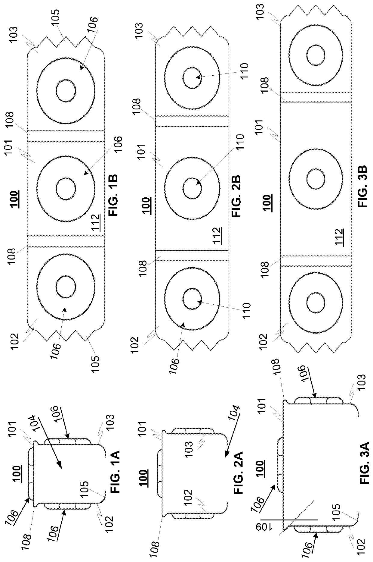
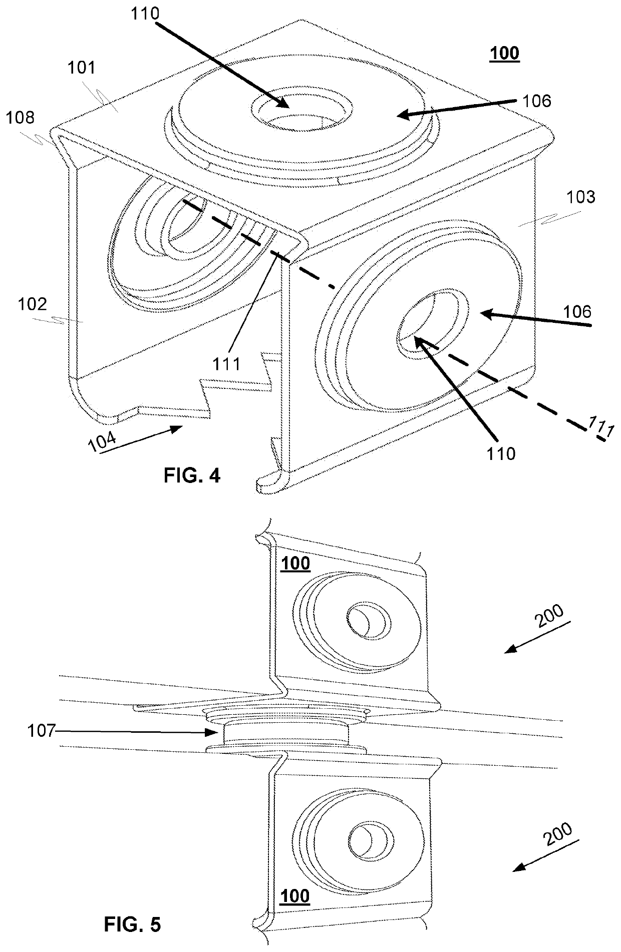
[0025]FIGS. 1A-3B and 4 illustrate a principle of exemplary devices 100 of different sizes for fastening elements 200, and FIG. 5 an example of devices used for fastening elements to each other according to an advantageous embodiment of the invention. The fastening device 100 comprises a planar top portion 101 and two side portions 102, 103, which are coupled with said planar portion at one end via an angle portion 108. The side portions form a receiving opening 104 for receiving the element 200 between the side portions, as is described elsewhere in this document. The angle portion 108 is advantageously inclined to extending towards the opening 104 and intersecting a normal 109 of said top planar portion at least in the end portion of said planar portion, as can be seen in FIG. 3A.

[0026]The side portions both comprise at least one or more tooth / teeth 105, which are inclined towards the opening 104 and the element 200 when the device is in use.

[0027]The top planar and side portions ...


PUM


Abstract

A fastening device for fastening soft surfaced elements to each other comprises a planar top portion and two side portions. The side portions are coupled with the planar portion at one end via an angle portion, and are arranged essentially perpendicularly in relation to said planar top portion and essentially parallel with each other thereby forming a receiving opening for receiving said element between the side portions. In addition the side portions both comprise at least one tooth, which is inclined towards the opening and the element in use and thereby arranged to fasten, such as via friction or via penetration into the surface of the element, and thereby fasten the device to the element. Moreover at least one of the portions comprises a protrusion portion for receiving, focusing and attaching a magnetic member to the device so to allow the device to be fastened to an external member via said magnetic member.

Description

PRIORITY[0001]This application is a U.S. national application of the international application number PCT / FI2017 / 050346 filed on May 4, 2017 and claiming priority of Finnish application No. 20165384 filed on May 4, 2016 the contents of all of which are incorporated herein by reference.TECHNICAL FIELD OF THE INVENTION[0002]The invention relates to a fastening device for fastening elements, and in particularly soft surfaced elements, such as wooden, surface peat, foam PVC, foam board, fibreboard, mineral wool or other wool or porosity material surface elements to each other as well as to external structures, such as walls or roofs. In addition the invention relates to a manufacturing method for manufacturing the fastening device.BACKGROUND OF THE INVENTION[0003]There are lots of different fastening solutions for fastening elements, such as for fastening board type elements to each other or to external structures, such as walls or roofs. Examples of these commonly known fastening solut...

Claims


Application Information

Patent Timeline
Patent Type & Authority Patents(United States)
IPC IPC(8): F16B2/24E04F13/08F16B5/00F16B5/06F16B1/00
CPCE04F13/0883F16B5/0008F16B2/245E04F2201/06E04F2201/0107F16B2001/0035F16B2005/0678F16B2200/83F16B5/004F16B17/008E04B9/248
Inventor KORHONEN, MIKA
Owner INNVOLVE CAPITAL OY
Why Eureka
Try Eureka