
Work vehicle composite panoramic vision systems

a composite and vision system technology, applied in the direction of vision systems, vehicular safety arrangements, pedestrian/occupant safety arrangements, etc., can solve the problems of limited visibility from the operator station or the cabin of the work vehicle, requiring a relatively high level of operator skill, and a sizable and complex machin

Active Publication Date: 2021-01-05
DEERE & CO
View PDF17 Cites 3 Cited by
  • Summary
  • Abstract
  • Description
  • Claims
  • Application Information

AI Technical Summary

Benefits of technology

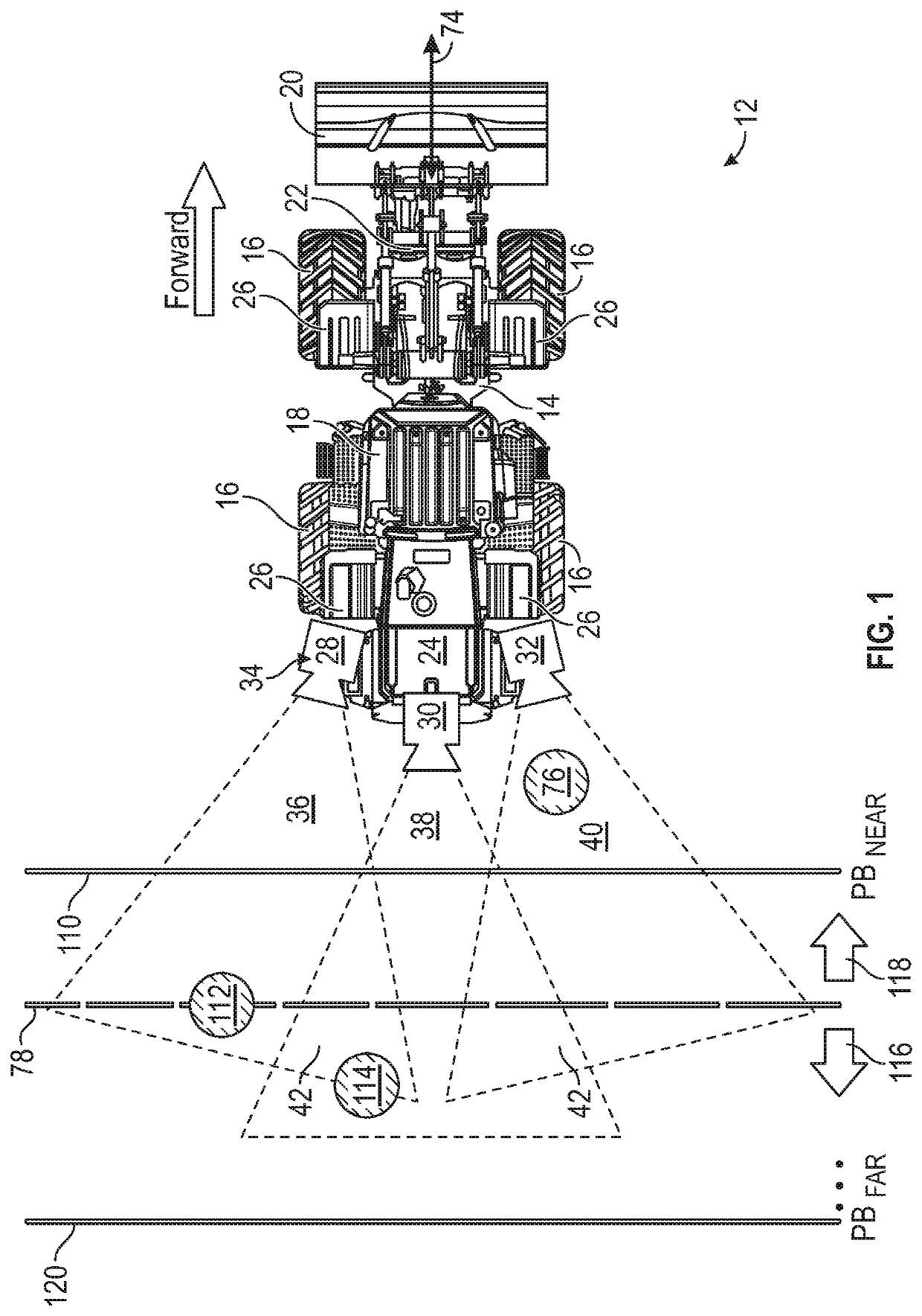
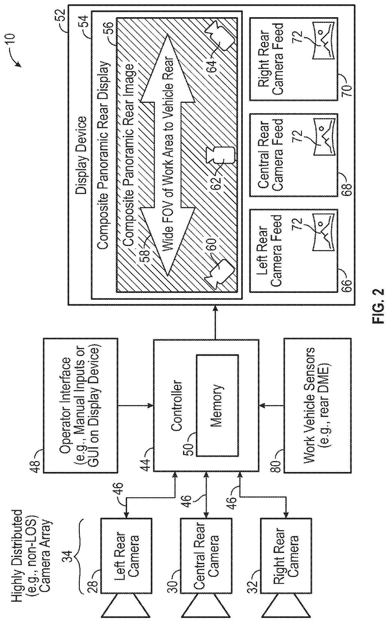
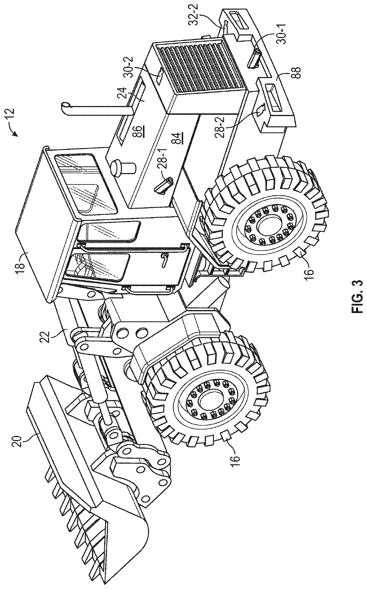
The patent text describes a composite panoramic vision system for work vehicles that generates a consolidated image of the vehicle's exterior environment using camera feeds captured by a camera array mounted on the vehicle. The system includes a display device, a vehicle-mounted camera array, and a controller. The controller receives the camera feeds, generates the consolidated panoramic image, and presents it on the display device for viewing by an operator of the vehicle. The system can also include a right rear, central rear, and left rear vehicle cameras to capture the vehicle's exterior environment from different angles. The technical effect of the composite panoramic vision system is to provide a wide-angle view of the work vehicle's exterior environment, enhancing visibility and safety for operators.

Problems solved by technology

Work vehicles utilized within construction, agriculture, forestry, mining, and other industries commonly operate in challenging work environments.
A given work vehicle may be a sizable and complex machine, requiring a relatively high level of operator skill to control the various functions of the work vehicle, in many instances including the movement of boom-mounted implements or other end effectors.
Concurrently, visibility from the operator station or cabin of the work vehicle may be limited by the chassis of the work vehicle, by the positioning of a bucket or other end effector relative to the cabin, and other visual hinderances.

Method used


Image

  • Work vehicle composite panoramic vision systems
  • Work vehicle composite panoramic vision systems
  • Work vehicle composite panoramic vision systems

Examples


Embodiment Construction

[0015]Embodiments of the present disclosure are shown in the accompanying figures of the drawings described briefly above. Various modifications to the example embodiments may be contemplated by one of skill in the art without departing from the scope of the present invention, as set-forth the appended claims. As appearing herein, the term “exterior environment” and the term “surrounding environment” are utilized interchangeably to broadly refer to a work environment or area exterior to a work vehicle, whether generally located to the front, to a side, or to the rear of the work vehicle, or any combination thereof. Further, the term “display” refers the composite imagery or “picture” generated on the screen of a display device, while the term “display device” refers to an image-generating device on which a display is presented, such as the below-described composite panoramic display.

Overview

[0016]As previously mentioned, certain work vehicles can be equipped with vision systems incl...


PUM


Abstract

A composite panoramic vision system utilized onboard a work vehicle includes a display device, a vehicle-mounted camera array, and a controller. The vehicle-mounted camera array includes, in turn, first and second vehicle cameras having partially overlapping fields of view and positioned to capture first and second camera feeds, respectively, of the work vehicle's exterior environment from different first vantage points. During operation of the composite panoramic vision system, the controller receives the first and second camera feeds from the first and second cameras, respectively; generates a composite panoramic image of the work vehicle's exterior environment from at least the first and second camera feeds; and then presents the composite panoramic image on the display device for viewing by an operator of the work vehicle.

Description

CROSS-REFERENCE TO RELATED APPLICATION(S)[0001]Not applicable.STATEMENT OF FEDERALLY SPONSORED RESEARCH OR DEVELOPMENT[0002]Not applicable.FIELD OF THE DISCLOSURE[0003]This disclosure relates to embodiments of a work vehicle vision system, which generates composite panoramic imagery of a work vehicle's surrounding environment from multiple camera feeds captured by a vehicle-mounted camera array.BACKGROUND OF THE DISCLOSURE[0004]Work vehicles utilized within construction, agriculture, forestry, mining, and other industries commonly operate in challenging work environments. Operators are often required to carefully navigate such work vehicles, while performing various tasks and avoiding surrounding structures, neighboring work vehicles, and other obstacles. A given work vehicle may be a sizable and complex machine, requiring a relatively high level of operator skill to control the various functions of the work vehicle, in many instances including the movement of boom-mounted implement...

Claims


Application Information

Patent Timeline
IPC IPC(8): B60R11/04B60R21/015H04N5/232
CPCB60R11/04B60R21/01538H04N5/23238B60R2300/105B60R2300/107B60R2300/303H04N7/181H04N5/2624H04N13/243B60R1/00B60R2300/301B60R2300/304B60R2300/802B60R2300/8093H04N23/698H04N23/90E02F9/261H04N13/246H04N2013/0081E02F3/431H04N23/63
Inventor CZARNECKI, NATHANIEL M.HAGEMAN, JOHN M.KEAN, MICHAEL G.
Owner DEERE & CO
Learn More