Muzzle velocity correction

Active Publication Date: 2021-01-05
UNITED STATES OF AMERICA THE AS REPRESENTED BY THE SEC OF THE ARMY
View PDF19 Cites 0 Cited by
  • Summary
  • Abstract
  • Description
  • Claims
  • Application Information

AI Technical Summary

Benefits of technology

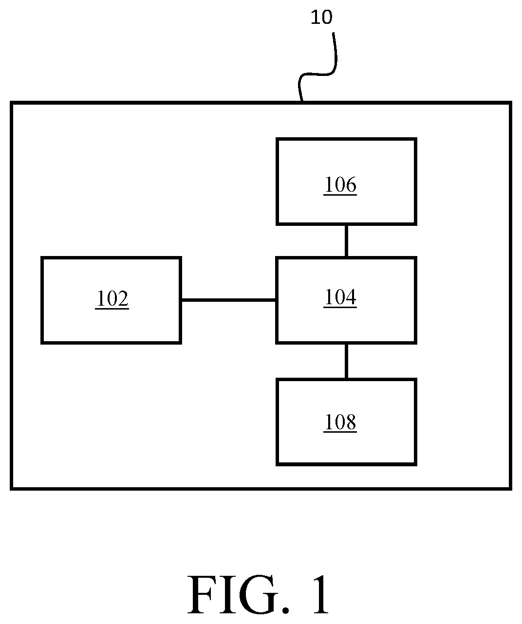
[0006]One aspect of the invention is a fuze for an airburst munition which adjusts an airburst time based on a corrected muzzle velocity measurement. The fuze comprises an on board acceleration sensor, an on board memory and an onboard processor. The on board acceleration sensor provides a measured acceleration to the on board processor. The on board memory encodes one or more processor-executable instructions. The on boar

Problems solved by technology

With target locations ranging out to thousands of meters and beyond, several errors stack up during the round's flight, causing the burst point location to miss the intended target beyond the effective lethal zone of the munition.
One

Method used


Image

  • Muzzle velocity correction
  • Muzzle velocity correction

Examples


Example

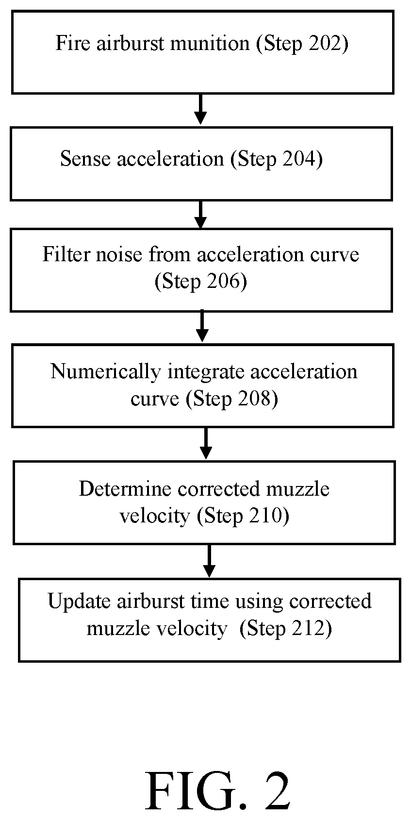
[0012]A fuze for an airburst munition determines a corrected muzzle velocity via an on board acceleration sensor and processor and corrects an airburst time, accordingly. Velocity calculations are made in real time which allows for timely update of airburst time thereby preventing error stack up due to muzzle velocity variations. Preliminary testing shows that the corrected muzzle velocity may be obtained within 500 milliseconds and reduces muzzle velocity error by over thirty percent.

[0013]Advantageously, the round requires no modification to the weapon system as was necessary in previous solutions. Further, the data obtained from the acceleration sensor is numerically integrated thereby providing a calculated value for velocity.

[0014]In contrast to conventional wisdom, the data is integrated via numerical integration by a central processing unit. Conventionally, on-board velocity determinations for other purposes, such as arming, were performed via analog signal processing techniq...


PUM


Abstract

A fuze for an airburst munition determines a corrected muzzle velocity via an on board acceleration sensor and processor and corrects an airburst time, accordingly. Velocity calculations are made in real time which allows for timely update of airburst time thereby preventing error stack up due to muzzle velocity variations.

Description

STATEMENT OF GOVERNMENT INTEREST[0001]The inventions described herein may be manufactured, used and licensed by or for the United States Government.FIELD OF THE INVENTION[0002]The inventions relates in general to munitions and in particular to airburst munitions.BACKGROUND OF THE INVENTION[0003]A common function of programmable fuzes is to set an “airburst” location that corresponds to a certain time and / or distance downrange. With target locations ranging out to thousands of meters and beyond, several errors stack up during the round's flight, causing the burst point location to miss the intended target beyond the effective lethal zone of the munition. One of the main contributors to this error stack up is the inability to program an airburst range / time in accordance with each individual round's muzzle velocity since the majority of existing programming techniques occur prior to firing.[0004]Existing methods that do include a muzzle velocity update often require multiple changes to...

Claims


Application Information

Patent Timeline
IPC IPC(8): F42C11/06F42B12/20
CPCF42C11/065F42B12/202
Inventor NEEB, ALEXANDERGINETTO, STEPHENSUROWIEC, ANDREW
Owner UNITED STATES OF AMERICA THE AS REPRESENTED BY THE SEC OF THE ARMY
Why Eureka
Try Eureka