Connector

a technology of connecting rods and connecting rods, applied in the direction of connection, electrical apparatus, coupling device connections, etc., can solve the problems of front holder unintentionally moving from temporary locking position to main locking position, sinks and voids are likely to occur, etc., to achieve the effect of suppressing sinks and voids and increasing rigidity of the arm

Active Publication Date: 2021-01-19
YAZAKI CORP
View PDF15 Cites 0 Cited by
  • Summary
  • Abstract
  • Description
  • Claims
  • Application Information

AI Technical Summary

Benefits of technology

[0016]According to one or more embodiments, it is possible to provide the connector capable of increasing the rigidity of the arm by reducing the length of the arm while effectively suppressing the generation of the sinks and the voids at the time of molding of the holder mounted on the housing.

Problems solved by technology

However, during transport, the front holder may unintentionally move from the temporary locking position to a main locking position due to contact with a peripheral member or the like.
However, if it is attempted to shorten the length of the locking arm by increasing the thickness of the base portion in the fitting direction of the front holder to which a root portion of the locking arm is connected, sinks and voids are likely to occur at the time of molding of the front holder due to an increase of the thickness.

Method used


Image

  • Connector
  • Connector
  • Connector

Examples


embodiment

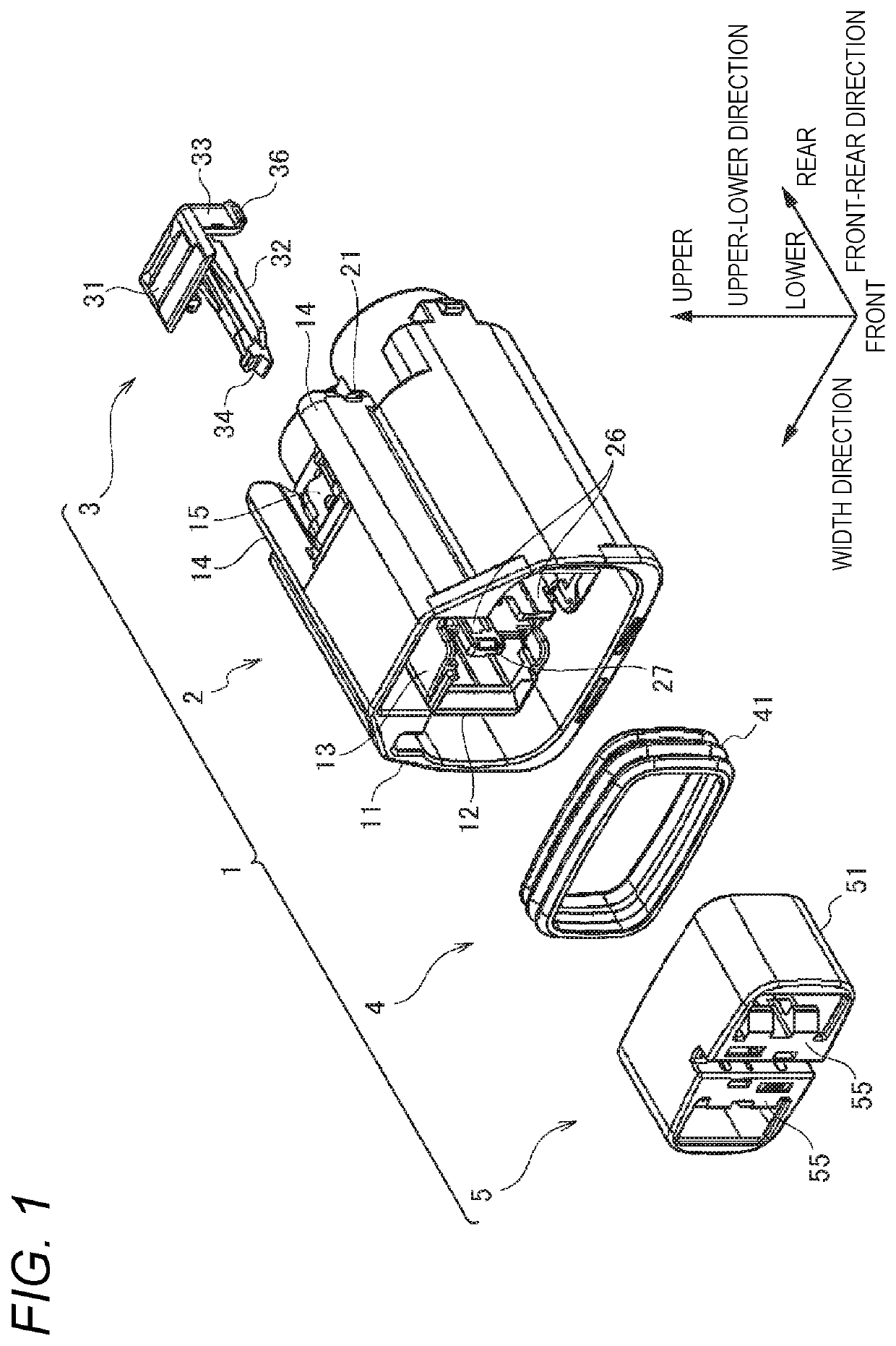
[0041]Hereinafter, a connector 1 according to an embodiment of the present invention will be described with reference to the drawings. Hereinafter, as shown in FIG. 1, a “front-rear direction”, a “width direction”, an “upper-lower direction”, “front”, “rear”, “upper”, and “lower” are defined for convenience of description. The “front-rear direction”, the “width direction”, and the “upper-lower direction” are orthogonal to one another. The front-rear direction coincides with a fitting direction of the connector 1 and a mating connector (not shown), and a front side (left side in FIG. 1) in the fitting direction in which the mating connector is fitted is a front side, and a back side (right side in FIG. 1) in the fitting direction opposite to the mating direction is a rear side.

[0042]As shown in FIG. 1, the connector 1 includes a housing 2, a slide holder 3 mounted on an upper portion of the housing 2, a packing 4 mounted on the housing 2 from the front side, and a front holder 5 moun...


PUM


Abstract

A connector includes a housing and a holder. The housing includes a terminal housing chamber housing a terminals and a support portion in which a first locking portion for locking the holder in the temporary locking position is formed. The holder is mounted on the housing so as to be movable in a fitting direction of the housing and a mating housing between a temporary locking position and a main locking position. The holder is configured to be immovable from the temporary locking position to the main locking position when the terminal inserted into the terminal housing chamber is in a halfway insertion position and is configured to be movable from the temporary locking position to the main locking position when the terminal is in a normal insertion position.

Description

CROSS REFERENCE TO RELATED APPLICATIONS[0001]This application claims priority from Japanese Patent Application No. 2018-164548 filed on Sep. 3, 2018, the entire contents of which are incorporated herein by reference.BACKGROUND OF THE INVENTIONField of the Invention[0002]The present invention relates to a connector.Description of Related Art[0003]In the related art, it is widely known that a connector including a housing provided with a terminal housing chamber for receiving a terminal is provided with a front holder for detecting a halfway insertion state of the terminal inserted into the terminal housing chamber (see, for example, Patent Literature 1).[0004]The front holder is mounted on the housing so as to be movable in a fitting direction of the housing and a mating housing between a temporary locking position and a main locking position. The front holder is configured to be movable from the temporary locking position to the main locking position when the terminal is in a normal...

Claims


Application Information

Patent Timeline
Patent Type & Authority Patents(United States)
IPC IPC(8): H01R13/436H01R13/502
CPCH01R13/4368H01R13/5025H01R13/4365H01R13/502H01R13/506
Inventor SAWAIRI, KAORU
Owner YAZAKI CORP
Why Eureka
Try Eureka