Optical fiber endface inspection with optical power measurement

a technology of optical power measurement and endface inspection, which is applied in the direction of optical elements, optical apparatus testing, instruments, etc., can solve the problems of increased risk of potential contamination of the connector endface, degraded signal integrity, and additional handling of optical-fiber connectors, so as to improve the optimization of signal light beam capture, and improve the stability of optical power measuremen

Active Publication Date: 2021-01-26
EXFO
View PDF12 Cites 0 Cited by
  • Summary
  • Abstract
  • Description
  • Claims
  • Application Information

AI Technical Summary

Benefits of technology

[0010]Positioning the optical power meter device outside of the imaging system of the inspection microscope advantageously allows optimization of the optical design of the optical power measurement assembly without affecting the optical design of the imaging assembly of the inspection microscope, which is optimized for connector endface inspection. As will be understood, the optical spectrum of light used in endface inspection (referred to herein as the inspection light beam) is different from the optical spectrum of light of which the optical power is to be measured (referred to herein as the signal light beam). Because the focal length of lenses typically varies with wavelength, objective optics of the inspection microscope has different focal lengths for the signal light beam and the inspection light beam. The objective optics and the focusing function of the inspection microscope is not optimized for capturing and focusing the signal light beam (the imaging assembly is configured to focus the inspection light beam on the image sensor, not the signal light beam). Redirecting or otherwise splitting the signal light beam from the inspection light beam before it reaches objective optics of the optical-fiber connector endface inspection microscope allow better optimization of the signal light beam capture and focusing on the optical power detector. Furthermore, if the signal light beam were to pass through the objective optics and focusing function, its focus on the optical power detector would be caused to vary, thereby causing variability in the optical power measurement responsivity. Redirecting or otherwise splitting the signal light beam before it reaches the objective optics obviates this issue as a whole. Minimizing the number of optical components through which the signal light beam passes also provides better stability in optical power measurement responsivity.
[0011]In some embodiments, the optical power meter device is releasable from the optical-fiber connector endface inspection microscope. Such configuration may advantageously allow an existing inspection microscope without optical power measurement capability to be converted into a system having integrated optical power measurement capability such that both endface inspection and optical power measurement may be conducted using a common connection port, without modifying the existing optical-fiber connector endface inspection microscope. In some embodiments, the optical power meter extension unit can be retrofitted to inspection microscopes that are already in possession of customers or end users without any need to return the existing inspection microscope to manufacture or maintenance. A releasable optical power meter device may also advantageously allow an inspection microscope to be used either with or without the optical power measurement capability, depending on user needs. In some further embodiments, the optical power meter extension unit may be configured to be also usable as a standalone device, i.e., without an inspection microscope, in order to measure optical power measurement only.
[0024]In some embodiments, said housing structure may be releasably connectable to a microscope housing of the optical-fiber connector endface inspection microscope via said second end. Such configuration may advantageously allow an existing optical-fiber connector endface inspection microscope without optical power measurement capability to be converted into a system having integrated optical power measurement capability, without modifying the existing optical-fiber connector endface inspection microscope.

Problems solved by technology

Indeed, any contamination of or damage on the mating surface of an optical-fiber connector may severely degrade signal integrity.
Of course, additional handling of optical-fiber connectors increases the risk of potential contamination of the connector endface.
Furthermore, if the signal light beam were to pass through the objective optics and focusing function, its focus on the optical power detector would be caused to vary, thereby causing variability in the optical power measurement responsivity.

Method used


Image

  • Optical fiber endface inspection with optical power measurement
  • Optical fiber endface inspection with optical power measurement
  • Optical fiber endface inspection with optical power measurement

Examples


Embodiment Construction

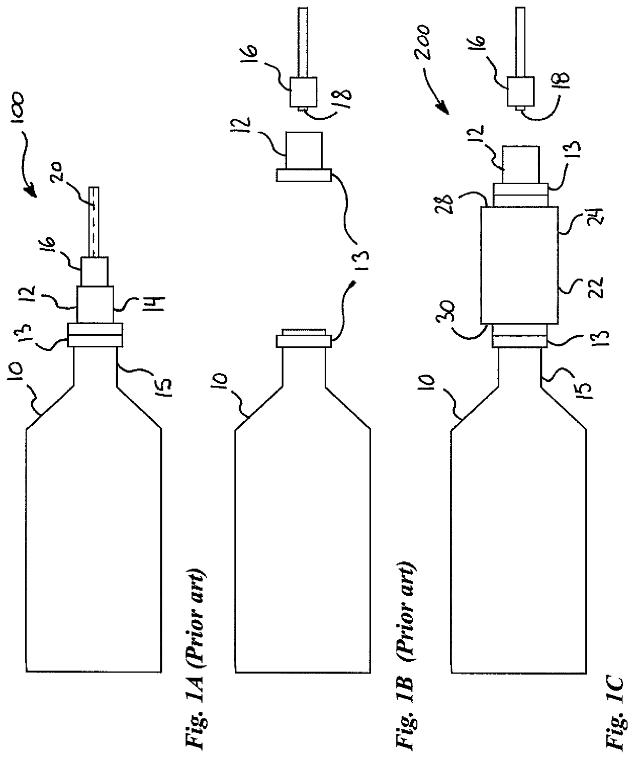
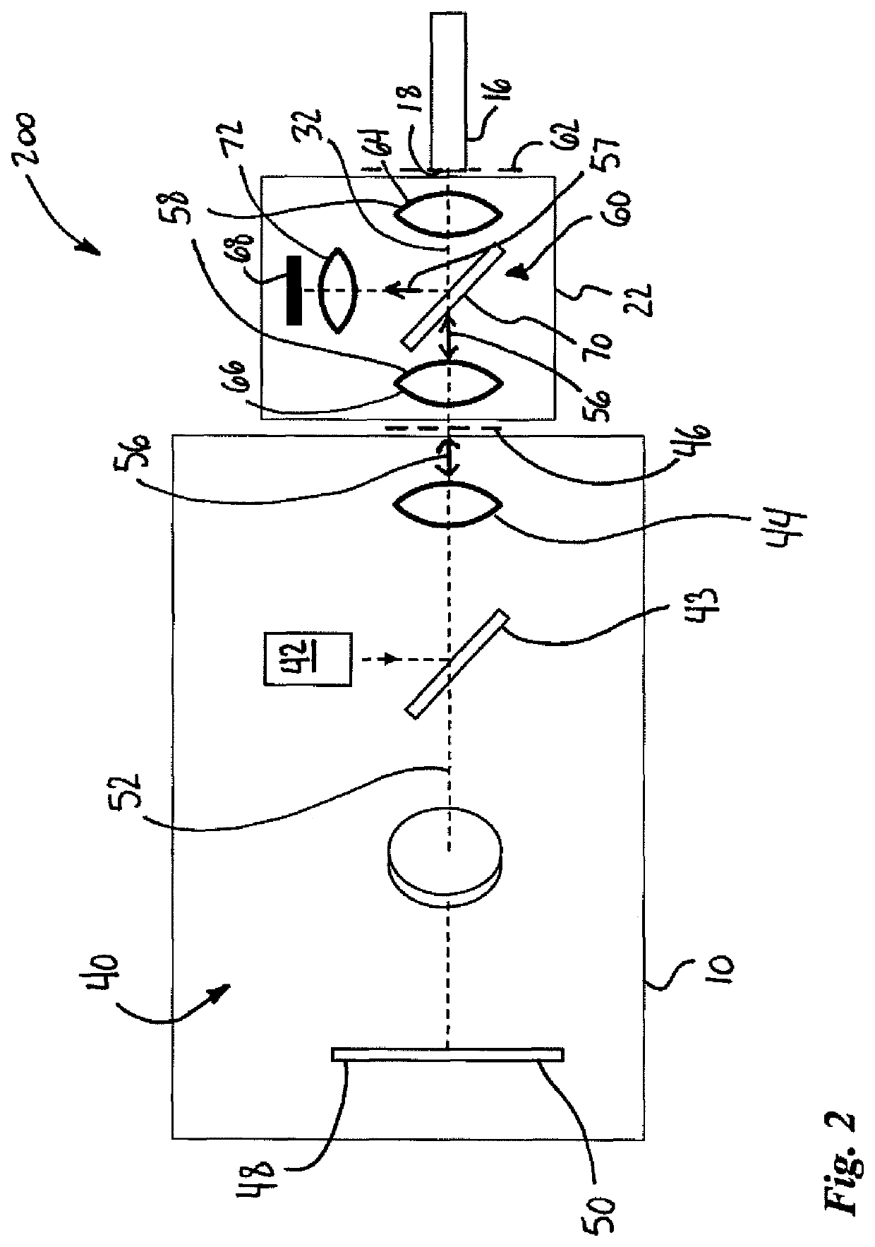
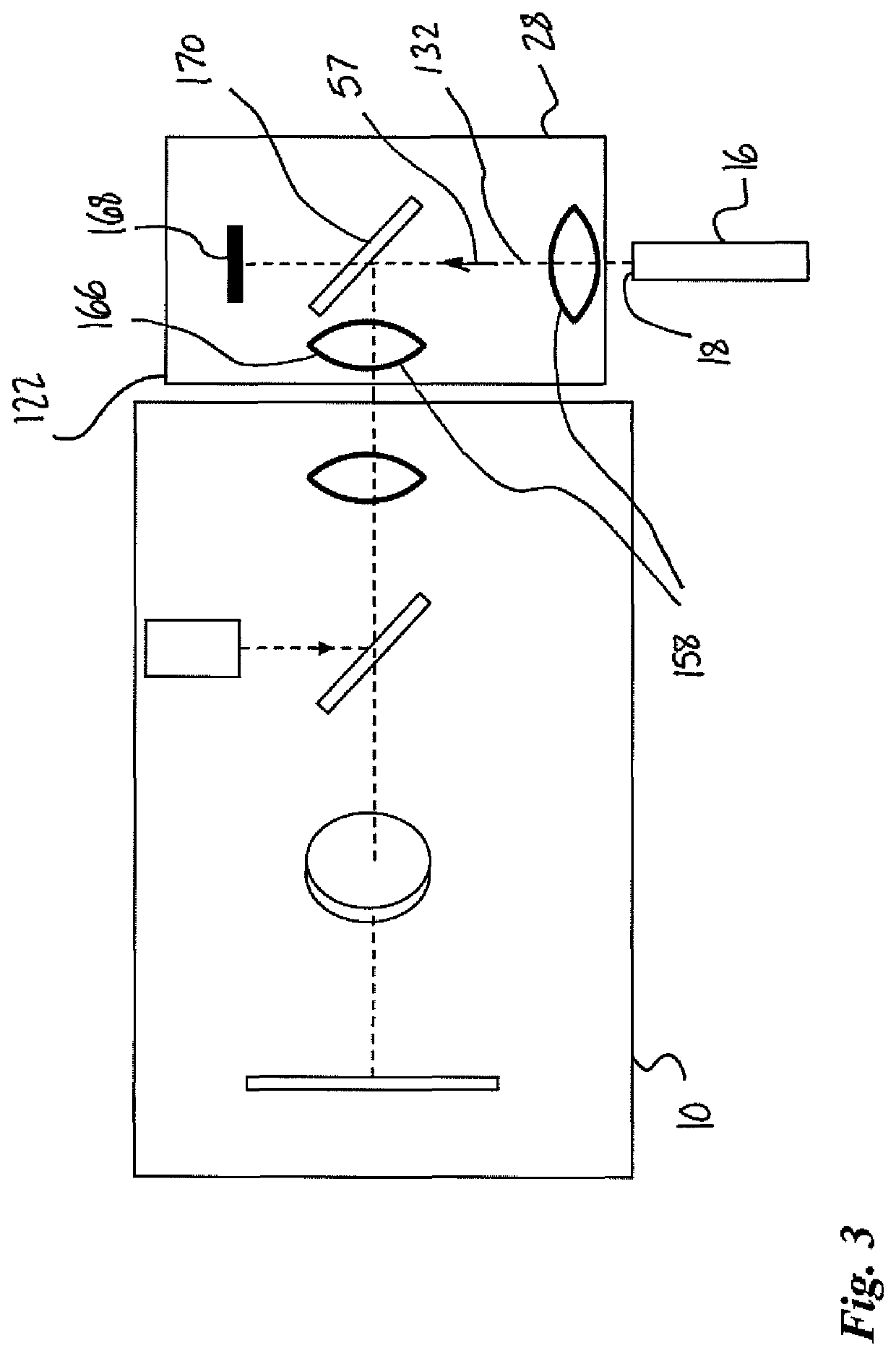
[0056]Optical connectors normally need to be inspected when they are connected and disconnected from one another. Typically, the procedure involves sequential steps of measuring an optical power value using an optical power detector and visually inspecting the optical-fiber connector endface using a fiber inspection microscope. However, undesirable particles can be deposited on the endface of the optical fiber while manipulating the optical fiber from the fiber inspection probe to the optical power detector, for instance. To circumvent this drawback, some have proposed fiber inspection probes adapted to inspect optical-fiber connector endfaces, which would incorporate both an optical-fiber endface imaging assembly and an optical power detection assembly. Such inspection probes would allow performing the two steps mentioned above in a single step, thus reducing the risk of contamination. However, such solutions imply a redesign of the existing inspection microscopes in order to intro...


PUM

PropertyMeasurementUnit
wavelengthsaaaaaaaaaa
optical power measurementaaaaaaaaaa
optical poweraaaaaaaaaa

Abstract

There is provided an optical-fiber connector endface inspection microscope system comprising optical power measurement capability, wherein optical power measurement is provided via an optical power meter device implemented within an extension unit positioned along an optical path between the inspected optical-fiber connector endface and the optical-fiber connector endface inspection microscope, i.e. between the inspected optical-fiber connector endface and objective optics of the optical-fiber connector endface inspection microscope.

Description

CROSS-REFERENCE TO RELATED APPLICATIONS[0001]This application claims priority under 35 USC § 119(e) of U.S. provisional patent application(s) 62 / 688,558 filed Jun. 22, 2018; the specifications of which is hereby incorporated by reference.TECHNICAL FIELD[0002]The present description generally relates to optical-fiber connector endface inspection, and more particularly, to optical-fiber connector endface inspection microscopes comprising both optical power measurement and connector endface inspection capabilities.BACKGROUND OF THE ART[0003]The quality and cleanliness of endfaces of optical-fiber connectors represent important factors for achieving expected system performance of optical communication networks. Indeed, any contamination of or damage on the mating surface of an optical-fiber connector may severely degrade signal integrity. Optical-fiber connector endface inspection microscopes are commonly employed to inspect the endface of an optical-fiber connector at installation or d...

Claims


Application Information

Patent Timeline
Patent Type & Authority Patents(United States)
IPC IPC(8): G01M11/08G01M11/00
CPCG01M11/088G01M11/30G02B6/385
Inventor BARIBAULT, ROBERT
Owner EXFO
Why Eureka
Try Eureka