Method of optimizing an electrical cabling

Inactive Publication Date: 2010-03-09
AIRBUS OPERATIONS (SAS)
View PDF9 Cites 8 Cited by
  • Summary
  • Abstract
  • Description
  • Claims
  • Application Information

AI Technical Summary

Benefits of technology

[0007]The present invention therefore has the objective of providing the means, for a given aircraft, that allow for limiting the mass of electrical cables required for the cabling of the various systems in the aircraft without, however, limiting the number and / or the positioning of said cables.
[0011]To best determine the section of cables to be used, the invention proposes in a preferred form of embodiment, prior to making the determination as to which section of cables to use, that the routing of the lines and cables be effected so as to allow for the calculation of the path to be taken by the various lines and cables. Thus, the knowledge of the path taken by the cables allows for a better optimization of the line since it is then possible to determine the type of cable being used (shielded or not, resistant to such and such a temperature, etc.). In the case of preliminary routing, said routing of lines and cables preferably allows for at least determining the approximate positioning of the cutouts separating two adjacent cables. In this manner, the length of each cable is known and the mass of the cables can better be determined.

Problems solved by technology

In this manner, it is possible to limit the section of cables that is used over certain parts of the line, while it is not possible, in contrast, to reduce a section over the entirety of the line.

Method used


Image

  • Method of optimizing an electrical cabling
  • Method of optimizing an electrical cabling
  • Method of optimizing an electrical cabling

Examples


Embodiment Construction

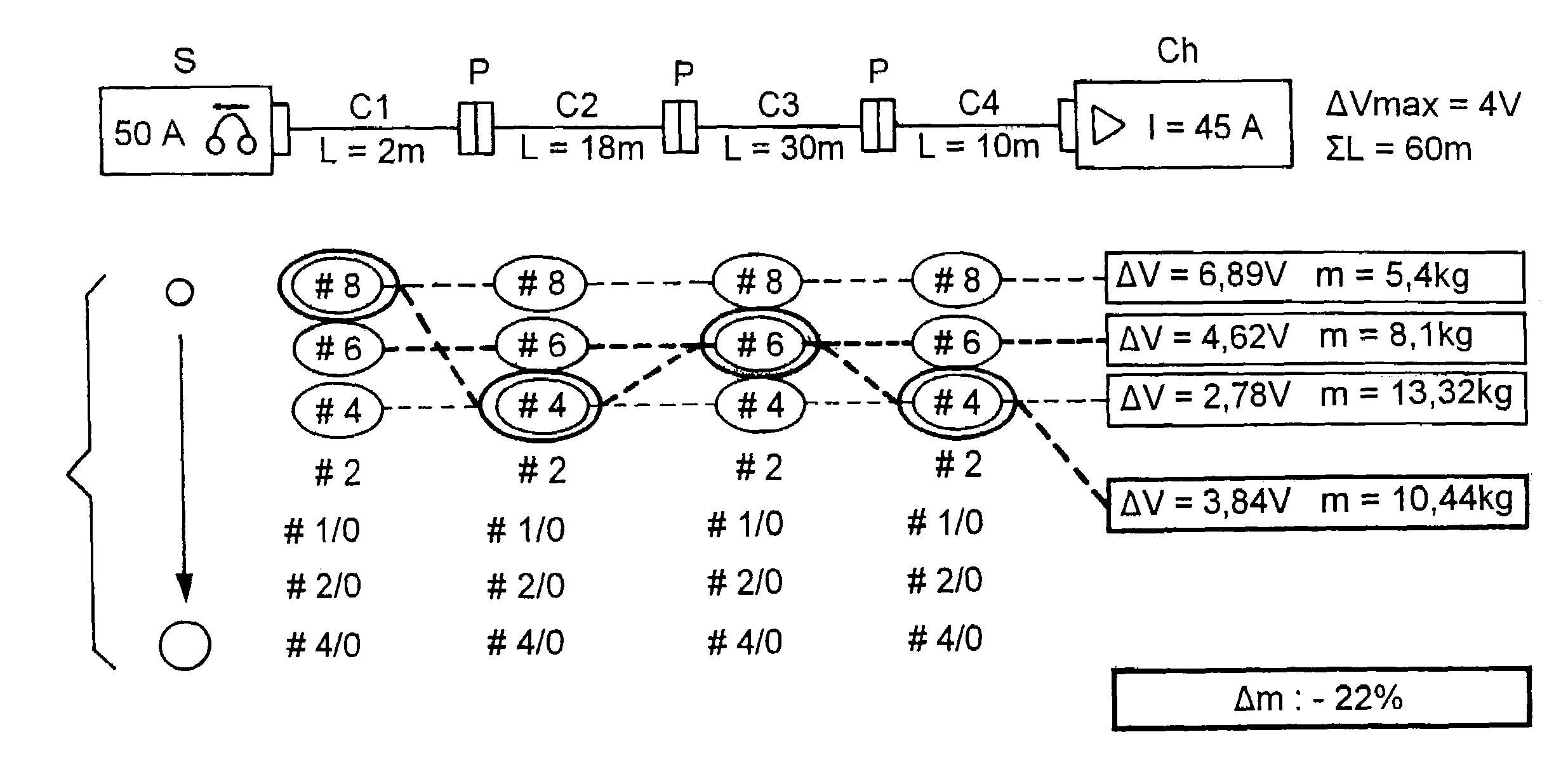
[0028]The drawing illustrates the utilization of a procedure in accordance with the invention for the implementation of the electric cabling in an aircraft. A similar procedure can be used in applications other than in aeronautics.

[0029]The following description shows how, in accordance with the invention, it is possible to reduce the overall mass of the cables in an electric network. In aircrafts, the increase in the number of systems installed on board as well as the increase in power consumption by multiple units of equipment in the aircraft lead to an increase in the mass of the electrical installations in the aircraft. To limit this increase, the invention proposes to optimize the mass of cables which connect the various systems installed on board and which supply power to the multiple units of equipment.

[0030]Of course, the optimized electrical network obtained must satisfy all of the safety standards without acting upon the levels of power consumed, nor on the number of syste...


PUM


Abstract

In this optimization procedure for the cabling, the characteristics of the cables used to connect a power source to a receiving charge are defined in function of the predetermined and environmental constraints. In the cases where a line realizing the link between the power source and the receiving charge is comprised of several distinct cables connected through cutouts, the section of cables is dimensioned for each cable in the line, independently of the other cables, and is then optimized while taking the overall constraints of the line into account.

Description

CROSS-REFERENCE TO RELATED APPLICATIONS[0001]This application claims priority to French Application No. 04 03468, filed Apr. 2, 2004, the entire content of which is hereby incorporated by reference.BACKGROUND OF THE INVENTION[0002]1. Field of the Invention[0003]The present invention concerns an optimization procedure for the electric cabling, more specifically, in the field of aeronautics.[0004]2. Discussion of the Background[0005]In aircrafts, the number of systems installed on board continuously increases over time. This increase is aimed at obtaining airplanes that are safer and better in performance. However, it leads to an increase in the number of cables that are present in an aircraft. With time, this implies the constant growth in the mass of electrical cables installed on board of an airplane.[0006]This supplementary mass installed on board is a handicap for any given aircraft. When the no-load weight of the aircraft is increased, then one must either provide for a more pow...

Claims


Application Information

Patent Timeline
Patent Type & Authority Patents(United States)
IPC IPC(8): G06F17/50B60R16/02H02G3/00
CPCB60R16/0207
Inventor BOUBEKEUR, JEAN-LUC
Owner AIRBUS OPERATIONS (SAS)
Why Eureka
Try Eureka