Method for driving micro-hybrid system for vehicle and energy storage unit, and hybrid system for implementing the same

a hybrid system and vehicle technology, applied in the auto industry, can solve problems such as destructive consequences and recharge the pack of super condensers

Active Publication Date: 2013-03-19
VALEO EQUIP ELECTRIC MOTEUR
View PDF10 Cites 6 Cited by
  • Summary
  • Abstract
  • Description
  • Claims
  • Application Information

AI Technical Summary

Benefits of technology

[0015]According to a first aspect, the object of the present invention is to provide a method for driving a new type of micro-hybrid system with braking recovery, which enables the system to be better optimized by offering the possibility of driving, wherein the effective state of the electric energy storage unit is taken into account.
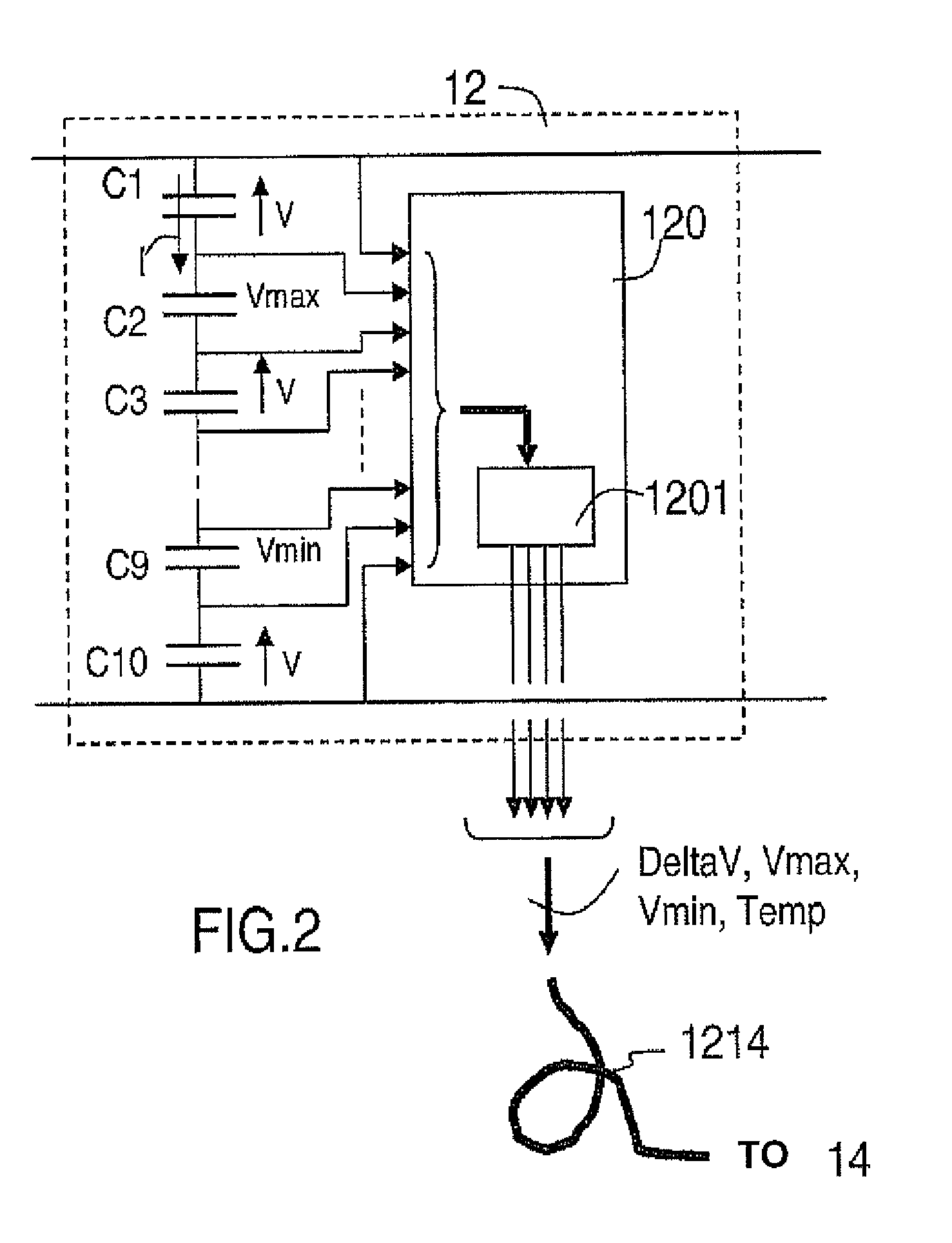
[0026]the method also includes the steps of: deriving a first difference in maximum voltage between the elementary cells based on the read elementary voltages when no significant current circulates in the electric energy storage unit, injecting into the electric energy storage unit a predetermined current over a predetermined short length of time, deriving a second difference in maximum voltage between the elementary cells based on the read elementary voltages during the injection of current and deriving the differential parasitic resistance data based on the difference between the first and second variations in voltage and based on the intensity level of the current of short duration.

Problems solved by technology

Thus, for example, if the vehicle is not used over long periods of time, the balance circuits continue to ensure symmetrical discharge from the pack of super condensers, ideally down to 0 V. Indeed, it is desirable that the pack of super condensers always remains balanced (especially with very low voltage) because, when the vehicle is restarted, the need to recharge the pack of super condensers as quickly as possible can have destructive consequences, on account of serious imbalances, if the discharge was not correctly followed through down to very low levels (2 V for example).

Method used


Image

  • Method for driving micro-hybrid system for vehicle and energy storage unit, and hybrid system for implementing the same
  • Method for driving micro-hybrid system for vehicle and energy storage unit, and hybrid system for implementing the same
  • Method for driving micro-hybrid system for vehicle and energy storage unit, and hybrid system for implementing the same

Examples


Embodiment Construction

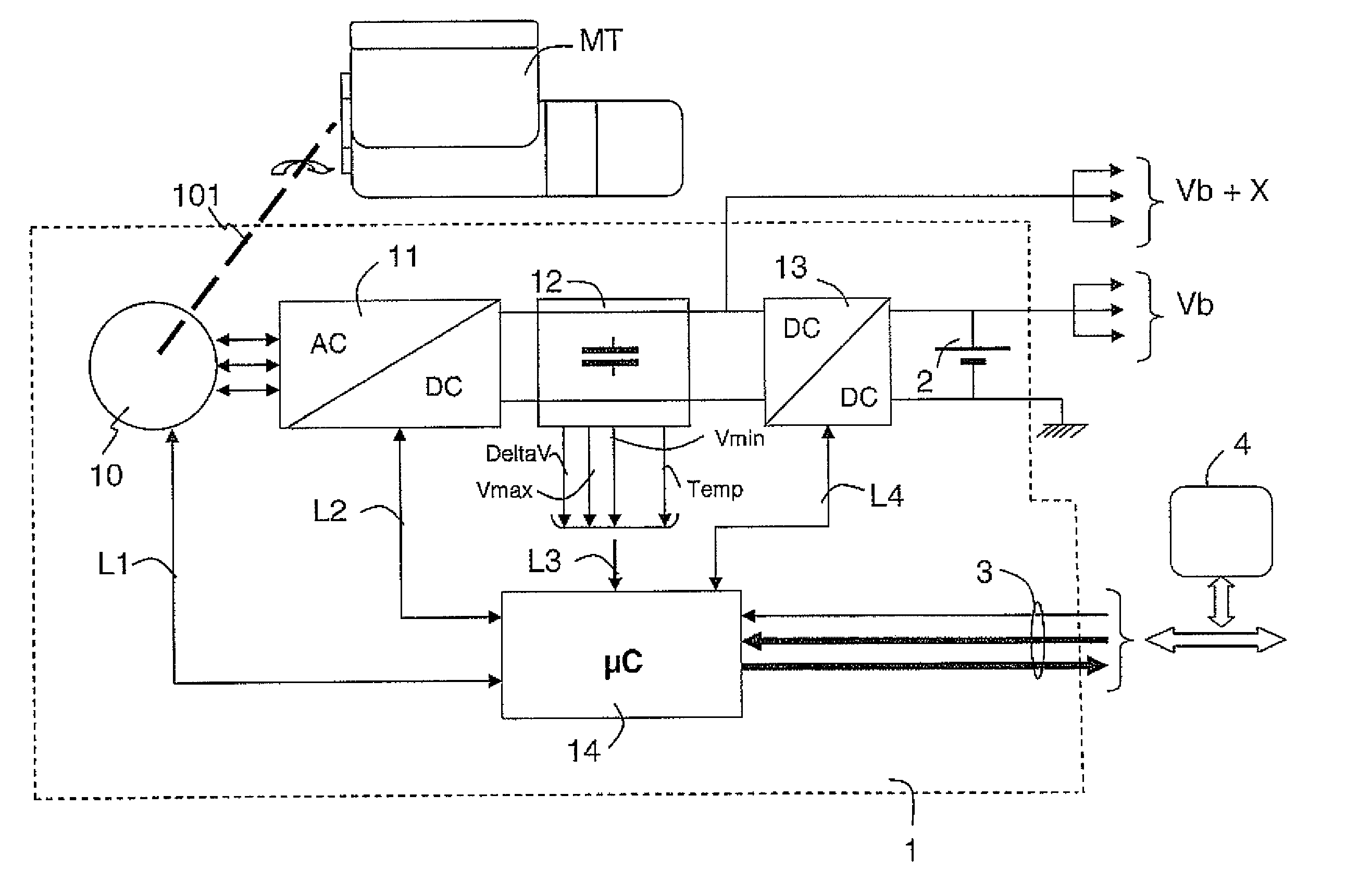
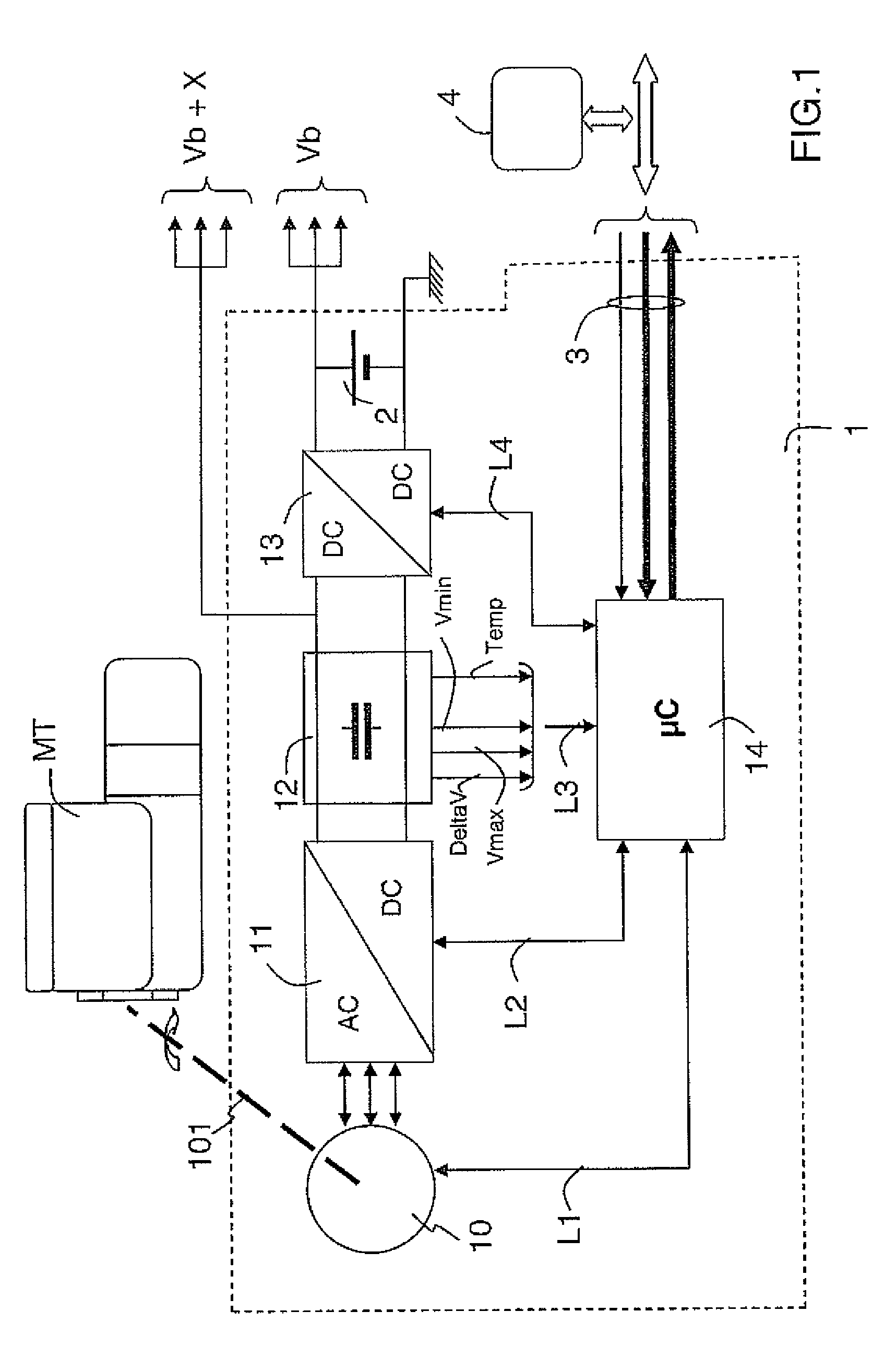
[0043]With reference to FIG. 1, a particular embodiment 1 of a micro-hybrid system with braking recovery according to the invention is now described.

[0044]As shown in FIG. 1, in this particular embodiment, the micro-hybrid system 1 according to the invention primarily includes an electrical rotating machine 10, a reversible AC-DC voltage converter 11, a capacitive electric energy storage unit 12, a DC-DC voltage converter 13 and a microcontroller 14.

[0045]The micro-hybrid system 1 is connected to an on-board dual voltage electrical network of the vehicle able to provide a low DC voltage Vb and a high floating DC voltage Vb+X.

[0046]The low DC voltage Vb is generally that of 12 V from a lead-acid battery 2 equipping the vehicle. Preferably, the Vb voltage can be used to feed consumers in the vehicle requiring a relatively stable voltage level, such as lighting and signalling devices.

[0047]In this particular embodiment, the DC voltage Vb+X varies for example between 12 and 60 V and is ...


PUM

PropertyMeasurementUnit
voltageaaaaaaaaaa
DC voltage Vbaaaaaaaaaa
DC voltageaaaaaaaaaa

Abstract

A micro-hybrid system (1) including an electric energy storage unit (12) and an electronic control unit (14). The storage unit includes a plurality of elementary cells mounted in series. A method includes the steps of: reading the elementary electric voltages of the elementary cells; deriving information on the state of the storage unit from the read voltages; and taking into account in the control unit the state information for defining an optimal driving of the micro-hybrid system. An electric energy storage unit and a micro-hybrid system with braking recovery is also disclosed.

Description

FIELD OF THE INVENTION[0001]The present invention is generally applicable in the automotive industry.[0002]More particularly, the invention relates to a method for driving a micro-hybrid system with braking recovery for a vehicle, the system including an electric energy storage unit and an electronic control unit, the electric energy storage unit including a plurality of elementary cells mounted in series.[0003]The invention also relates to a micro-hybrid system with braking recovery and an electric energy storage unit conceived for implementing the method.TECHNOLOGICAL BACKGROUND OF THE INVENTION[0004]In order to reduce the fuel consumption of vehicles and consequently the pollution which they generate, it is known to equip a vehicle with a micro-hybrid system, for example an alternator-starter, enabling a braking recovery mode.[0005]Equally, a micro-hybrid system of the above type comprising a reversible electrical rotating machine, a reversible AC-DC voltage converter, an electri...

Claims


Application Information

Patent Timeline
Patent Type & Authority Patents(United States)
IPC IPC(8): H01M10/44H01M10/46
CPCB60K6/485B60L11/1864B60W10/08B60W10/26B60W20/00B60W2510/244Y02T10/6226Y02T10/6278Y02T10/7005Y02T10/7061B60Y2400/112B60Y2400/114B60L58/21Y02T10/62Y02T10/70B60K6/46
Inventor RANIER, MARCMATT, JEAN-CLAUDE MATTSARDAT, PIERRE
Owner VALEO EQUIP ELECTRIC MOTEUR
Why Eureka
Try Eureka