
Automated cybersecurity threat detection with aggregation and analysis

a cybersecurity threat and automated detection technology, applied in the field of automated detection, aggregation and integration of cybersecurity threats, can solve the problems of limited intelligence pivoting, inability to push/pull to sensors, and inability to control the inclination of the inclination of the inclination of the inclination of the inclination of the inclination of the inclination of the inclination of the inclination of the inclination of the inclination

Active Publication Date: 2021-01-26
THREATQUOTIENT INC
View PDF11 Cites 9 Cited by
  • Summary
  • Abstract
  • Description
  • Claims
  • Application Information

AI Technical Summary

Benefits of technology

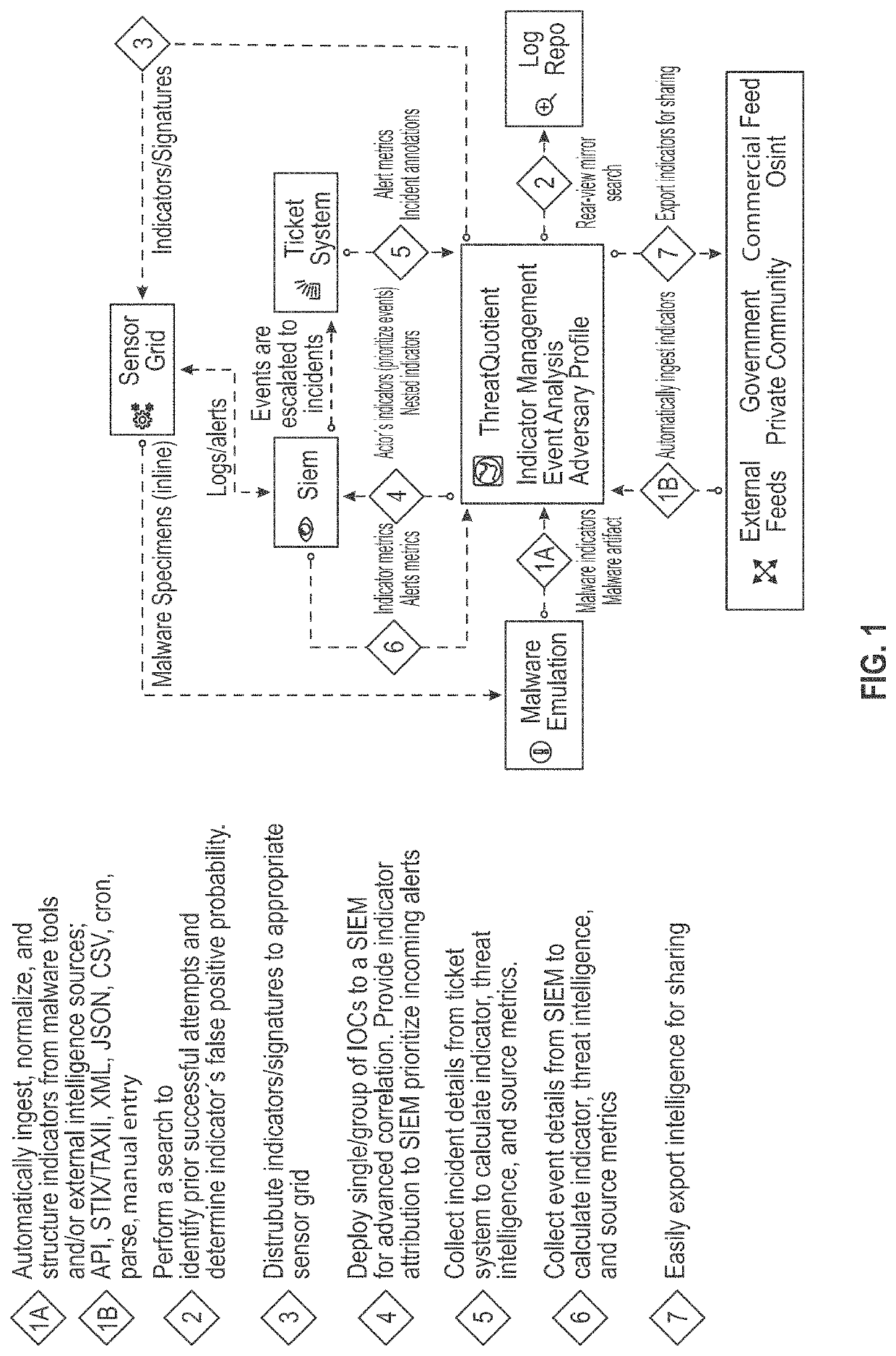
The patent describes a system and method for automated detection, aggregation, and integration of cybersecurity threat indicators, trends, tactics, techniques, and procedures (TTPs) to improve the efficiency and effectiveness of responding to cyber threats. The invention includes various modules that can be separated or combined into one physical entity or geographically located. The technical effects of the invention include improved automation and efficiency in detecting, analyzing, and responding to cyber threats, as well as better cross-platform and multi-format capabilities.

Problems solved by technology

Current cybersecurity threat indicator tracking and indication systems require that operators archive indicators in ad-hoc spreadsheets which often leads to version control issues, inability to push / pull to sensors, and limited intelligence pivoting, among other shortcomings.
Other solutions include internally developed solutions or a leveraged “shared tool.” These solutions often lead to a struggle to find internal expertise necessary to properly maintain, customize and manually update the tool to optimize the time and capabilities of an analyst.
These internally developed solutions generally lack cross-platform and multi-format capabilities.
Additionally, in known systems, differences in data formats, construction and data content of external threat feeds do not allow for automated compilation into a single format.
As a result, active information security threats cannot be mitigated efficiently, or at all, in some cases.

Method used


Image

  • Automated cybersecurity threat detection with aggregation and analysis
  • Automated cybersecurity threat detection with aggregation and analysis
  • Automated cybersecurity threat detection with aggregation and analysis

Examples


Embodiment Construction

[0024]In the following description of embodiments, reference is made to the accompanying drawings, which form a part hereof, and in which it is shown by way of illustration specific embodiments of claimed subject matter. It is to be understood that other embodiments may be used and changes or alterations, such as structural changes, may be made. All embodiments, changes or alterations are not departures from scope with respect to intended claimed subject matter. While the steps below may be presented in a certain order, in some cases the ordering may be changed so that certain inputs are provided at different times or in a different order without changing the function of the systems and methods described. The procedures described herein could also be executed in different orders. Additionally, various computations that are described below need not be performed in the order disclosed and other embodiments using alternative orderings of the computations could be readily implemented. I...


PUM


Abstract

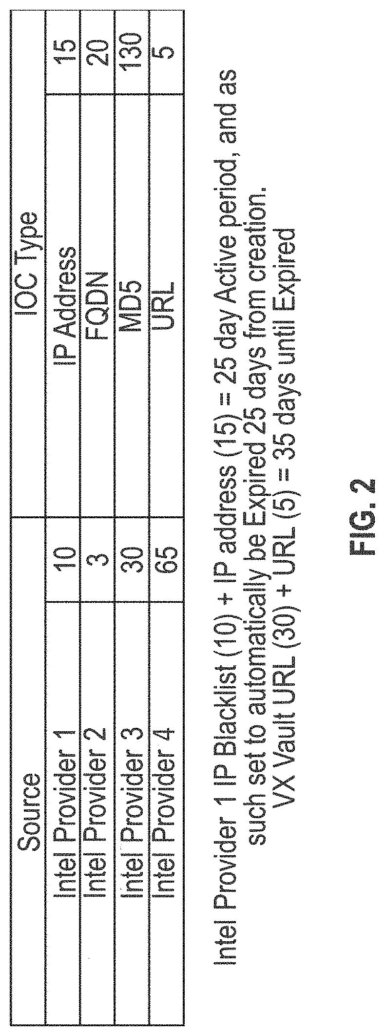
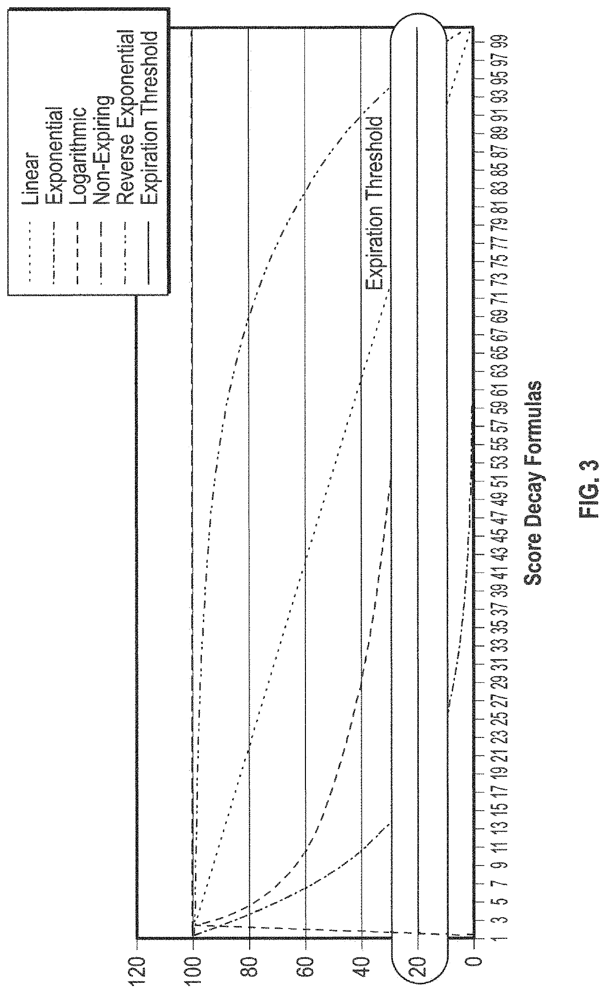
The systems and methods described herein generally relate to techniques for automated detection, aggregation, and integration of cybersecurity threats. The system ingests multiple data feeds which can be in one or numerous different formats. The system evaluates information based on defined scores to display to users threats and risks associated with them. The system also calculates decay rates for expiration of threats and indicators through various methods.

Description

CROSS-REFERENCE TO RELATED APPLICATIONS[0001]This application is a continuation-in-part of application Ser. No. 15 / 261,867, filed Sep. 9, 2016, which claims the benefit of U.S. Provisional Application No. 62 / 215,777, filed Sep. 9, 2015, the contents of each of which are herein incorporated by reference in their entireties. This application also claims the benefit of U.S. Provisional Application No. 62 / 594,014, filed Dec. 3, 2017, and U.S. Provisional Application No. 62 / 631,695, filed Feb. 17, 2018, the contents of each of which are herein incorporated by reference in their entireties.FIELD OF THE INVENTION[0002]The systems and methods described herein generally relate to techniques for automated detection, aggregation, and integration of cybersecurity threats.BACKGROUND OF THE INVENTION[0003]Current cybersecurity threat indicator tracking and indication systems require that operators archive indicators in ad-hoc spreadsheets which often leads to version control issues, inability to ...

Claims


Application Information

Patent Timeline
IPC IPC(8): G06F21/55G06F16/26G06F16/22G06F16/28
CPCG06F21/552G06F16/22G06F16/26G06F16/288G06F2221/034
Inventor TROST, RYANWARD, LEON
Owner THREATQUOTIENT INC
Learn More