Vise table

a vise head and table technology, applied in the field of vise tables, can solve the problems of time-consuming and time-consuming application of rotational force to the threaded mechanism, and achieve the effect of selectively facilitating the movement of the vise head block

Active Publication Date: 2021-02-16
THE STANLEY WORKS ISRAEL
View PDF19 Cites 2 Cited by
  • Summary
  • Abstract
  • Description
  • Claims
  • Application Information

AI Technical Summary

Problems solved by technology

The application of rotational force to the threaded mechanism is often a time-consuming task because the threaded mechanism often has a very small diameter in comparison to the distance that the movable jaw has to traverse.

Method used


Image

  • Vise table
  • Vise table
  • Vise table

Examples


Embodiment Construction

)

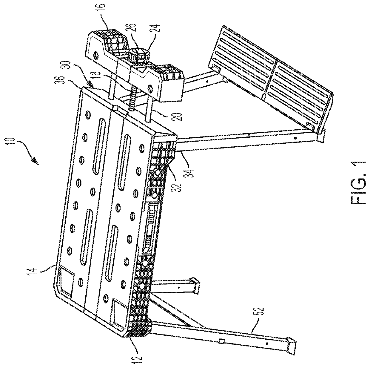
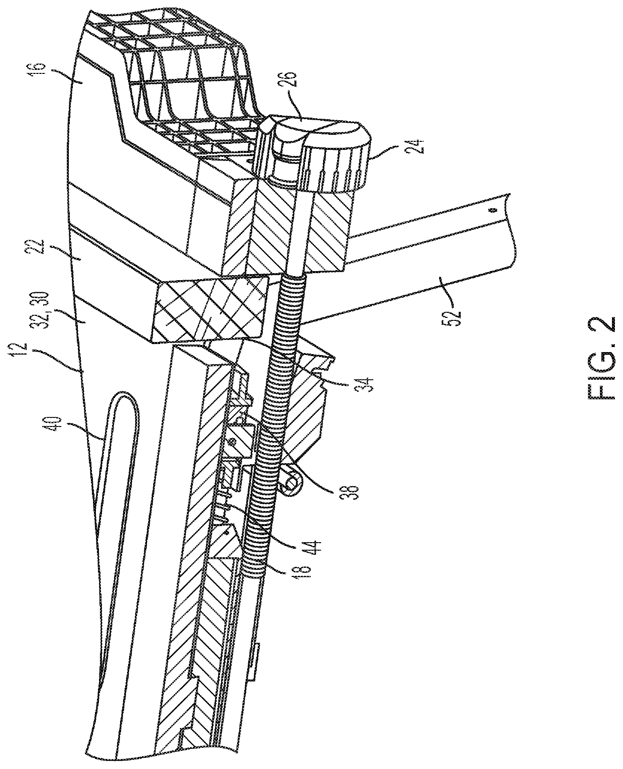
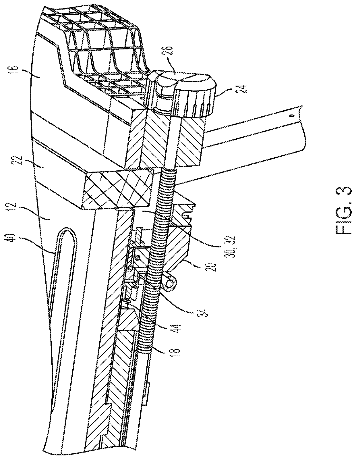
[0012]FIG. 1 illustrates a perspective view of a vise table 10. The vise table 10 includes a table block 12. The table block 12 has an upper working surface 14. The vise table 10 also includes a vise head block 16 coupled to the table block 12 via a threaded guide 18. In addition to the threaded guide 18, the vise head block 16 may also be coupled to the table block 12 via one or more guides 20. Vise head block 16 is configured to be movable between an open position and a closed position. Guide 20 may be configured to stabilize the movement of the vise head block 16 as it moved between the open position and the closed position. In the open position, the vise head block 16 is distal from the table block 12. In the closed position, the vise head block 16 is adjacent to the table block 12. Those skilled in the art will recognize that the vise table 10 is configured to hold an object 22, such as a piece of wood, between the vise head block 16 and the table block 12. (See FIGS. 2 and 3....


PUM


Abstract

The present invention relates to an integrated vise and work table. The disclosed vise table allows an operator to clamp an object in place so that the same can worked on in a hands-free method. The vise table includes a table block, a vise head block, a threaded guide, a rotator, and an activation mechanism that allows the operator to selectively vise in a threaded mode or in an unthreaded mode. In the threaded mode, the vise head block may only be moved by rotating a threaded guide. In the unthreaded mode, the vise head block may only be moved by applying force to the vise head block in the desired direction of movement.

Description

FIELD OF THE INVENTION[0001]The present invention relates to a vise table. More specifically the invention relates to a vise table having a mechanism wherein an operator can selectively move the vise head block in a threaded mode or an unthreaded mode.BACKGROUND OF THE INVENTION[0002]The general concept of a vise is well known. Typically, they are configured to secure an object in place and allow an operator to work on said object in a hands-free manner.[0003]Vises typically include a fixed jaw and a movable jaw. The moveable jaw is often connected to the fixed jaw by a threaded mechanism or screw. By applying rotational force to the threaded mechanism, an operator can move position the movable jaw such that it holds an object between the movable and fixed jaw. The application of rotational force to the threaded mechanism is often a time-consuming task because the threaded mechanism often has a very small diameter in comparison to the distance that the movable jaw has to traverse. I...

Claims


Application Information

Patent Timeline
Patent Type & Authority Patents(United States)
IPC IPC(8): B25B1/02B25B1/12B25H1/04
CPCB25B1/12B25B1/02B25H1/04B25H1/10B25H1/08B25B1/125
Inventor OMRY, ADARSAIGAUVKER, SHALOM
Owner THE STANLEY WORKS ISRAEL
Why Eureka
Try Eureka